

So far, we have discussed the fundamentals of vibration measurement over three installments. In this fourth installment, we will talk about the damping ratio.
減衰比ζは、振動の挙動に重要な役目を果たしており、自由振動(1 回目)では振動するか否かまたは振動した場合での振動が止まる速さに影響を与え、強制振動(2 回目)では共振周波数におけるピークの大きさに影響を与え、振動伝達率(3 回目)では共振周波数におけるピークの大きさや共振周波数を超えた周波数帯域での伝達率に影響を与えます。
今回(4 回目)では、FFTアナライザで実際に振動計測を行いその結果から減衰比ζを求める方法について説明します。
減衰を表現するパラメータは応用分野によっていろいろありますが、まず、対数減衰率から求める方法を紹介します。
対数減衰率δは、自由振動の減衰波形の隣り合う振幅比の自然対数として定義されます。
なぜ、自然対数なのか? それはもちろん、図1 にあるように、自由振動の振幅は指数関数的に減衰するからです。
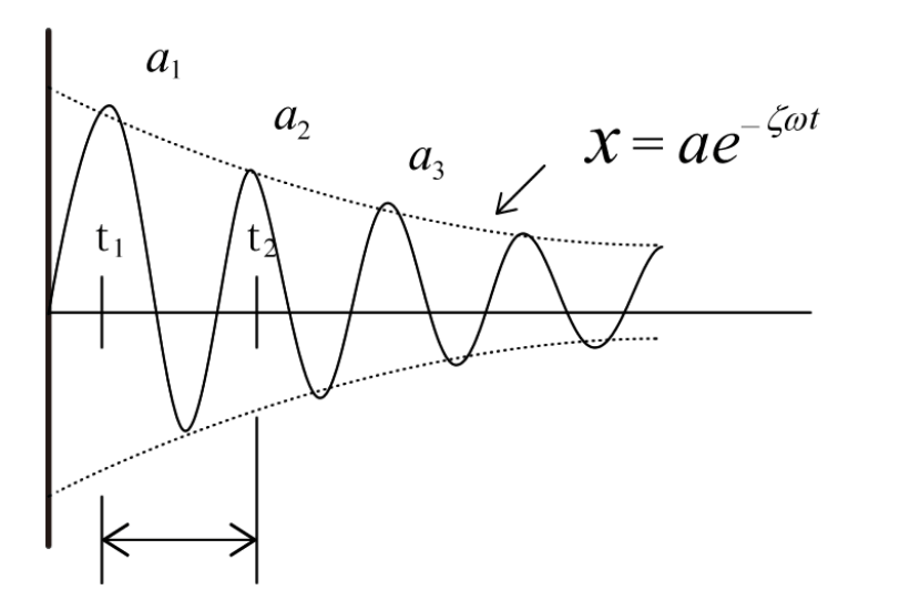
Figure 1: Damped Free Oscillation Waveform
図1 の減衰自由振動波形 x (t)は、
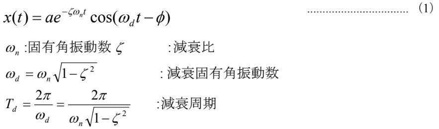
となります。
図1 において、対数減衰率δは
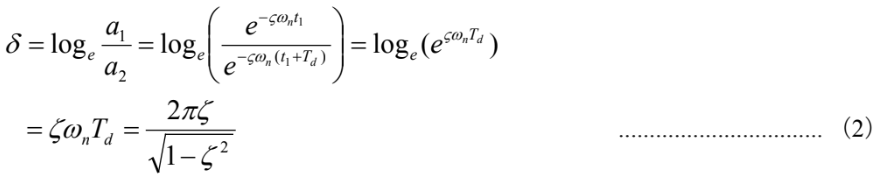
ここで、ζ<<1 ならば

Next, to determine the logarithmic decrement δ, first use the Hilbert transform to obtain the envelope of the damped waveform, then plot time on the horizontal axis and the logarithm of the amplitude on the vertical axis (Figure 2).
-

Figure 2: Graph showing the envelope of the damped waveform with the vertical axis displayed in dB.
対数減衰率 δ は、減衰周期 Td に対する傾きだから、dB 表示が常用対数だということに注意して、図2 の直線の傾きより、

Here, therefore

Using the Delta Search function of the FFT analyzer (DS-3000 Series), calculate the logarithmic decrement δ from equation (5).
Furthermore, from equation (3)

From the measured data and equation (5), the logarithmic decay rate δ can be calculated, and from equation (6), the damping ratio ζ can be determined.
Figure 3 shows an example where the damping time waveform of free vibration is measured by hammering, and then the logarithmic decay rate is calculated, followed by the determination of the damping ratio. Note that this figure utilizes the band-limiting function of the Hilbert transform to create a decay waveform for a single resonant frequency.
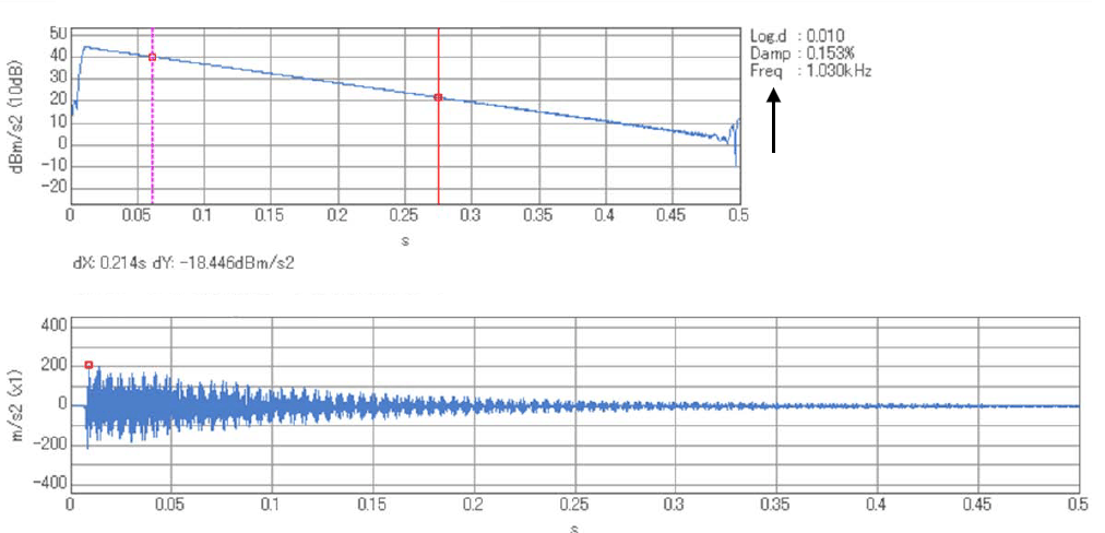
Figure 3: An example of calculating logarithmic decay rates and damping ratios from time waveform and envelope data.
Next, we will determine the damping ratio from the resonance peak of the frequency response function using the half-value width method.
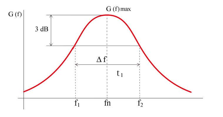
Figure 4: A diagram explaining the half-width method.
Let G(f) denote the frequency response function (compliance) of a single-degree-of-freedom system.

ここで、 fn :固有周波数 ζ :減衰比
図4において、共振周波数 fn の値 G(f)max から-3 dB(パワーで 1/2、振幅で 1/√2)となる点を f1 と f2、またΔf=f2-f1とします。
f1 と f2は近代的に fn ± ∆f / 2 とおけるので、 fnとの比は

If you substitute this value into equation (7) and take the reciprocal,

Also, the maximum value is modernly than the style
 Because it becomes (9), when substituted into the equation.

Transform the equation

Because it uses the bandwidth at 1/2 power, the method for determining the damping ratio using equation (11) above is called the half-power bandwidth method.
In addition to the half-power bandwidth method, the mdB method can also be considered. In this case,

Here,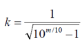
ちなみに、1 dB の時は、k=1.97 2 dB の時は、k=1.31 です。
半値幅法で、制振材料の評価パラメータで用いられる損失係数(loss factor)も求められます。履歴減衰を伴う減衰振動では、振動変位に比例する復元力を生じさせる複素弾性率 K’を定義して、実数部を K1、虚数部を K2とすると

Here,

This is the result. (Figure 5) This η is called the loss factor. The complex modulus K’ includes both the spring constant k and the viscous damping coefficient c in a single-degree-of-freedom system model. As shown in Figure 5, the loss factor is also called tan delta (tan δ).
-

Figure 5 Complex Elastic Modulus and Loss Factor
From the half-width method, the loss coefficient η can be calculated using the following formula.

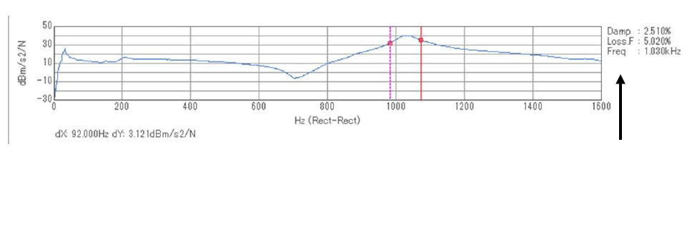
Figure 6 Empirical examples of damping ratios and loss coefficients measured by the half-width method.
図 6 は、FFT アナライザを使ってハンマリング法で計測した FRF(周波数応答関数)から、半値幅法により減衰比と損失係数を求めた例です。
As a summary of various parameters, Table 1 below shows a list of the relationships between the various parameters that represent damping characteristics.
Table 1: Interrelationships Among Various Parameters
| 減衰比 ζ |
対数減衰率 δ |
Q値 Q |
損失係数 η |
|
| z | — | 2πζ | 1 / 2ζ | 2ζ |
| δ | δ / 2π | — | π / δ | δ / π |
| Q | 1 / 2Q | π / Q | — | 1 / Q |
| η | η / 2 | πη | 1 / η | — |
注意1:本表は、ζ ≪ 1 とみなせる場合です。
注意2:Q値は、振動系が共振する場合、この共振の鋭さを表す量で、損失係数の逆数です。
[Keyword]
damping ratio, free vibration, forced vibration, resonance frequency, vibration transmission rate, logarithmic decrement, natural angular frequency, damped natural angular frequency, damping period, Hilbert transform, envelope, delta search function, half-width method, half-power band width method, loss factor, complex modulus of elasticity, spring constant, viscous damping coefficient, tan delta, tandelta, hammering method, Q value
Reference
“Introduction to Modal Analysis,” by Akio Nagamatsu, Corona Publishing Co., Ltd. (1994)
Ono Sokki Technical Report, “Coefficients Representing Damping Characteristics”
(Excerpt from the newsletter published on January 21, 2016)


