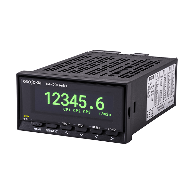
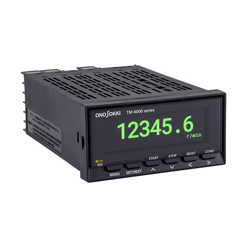
Digital Tachometer
TM-4000シリーズ
A new standard for tachometers, integrating four models.
We've completely revamped our lineup of Digital Tachometer.
The TM-3100 series has been redesigned, and the new "TM-4000 series" Digital Tachometer has been created, integrating a multi-function tachometer, reversible counter, and passage time/passage speed meter.
While inheriting the functions and performance of previous models, this device pursues high precision and high responsiveness. You can select the input format according to the external device or sensor you are connecting, and customize it by combining various functions such as analog output, comparator output, and DC power supply.
The TM-4000 series addresses the diversifying needs for rotational speed measurement and supports the realization of DX (Digital Transformation) and smart factory initiatives.

TM-4100 series
Basic 1-channel input
This new model offers improved basic performance while maintaining compatibility with previous models (TM-3100 series). You can continue using your existing sensors, cables, and mounting fixtures.
(Previous model: TM-3100 series)

TM-4200 series
2-channel input, rotation speed difference/speed
Redesigned with a more compact body. High-speed sampling of 1 ms enables accurate quality inspection and control of machinery.
(Previous model: TM-5100)

TM-4300 series
Calculation and addition/subtraction counter
(Reversible counter)
The cumulative pulse count has been significantly increased, and the display now has 7 digits.
Improved quality through precise positioning and line control of winding length.
(Previous model: RV-3150)

TM-4400 series
Passing time/passing speed
The measurement cycle range has been expanded (0.1 ms to 3600 s).
Simultaneously measure the time and speed of travel between two points.
(Previous model: ST-1210)
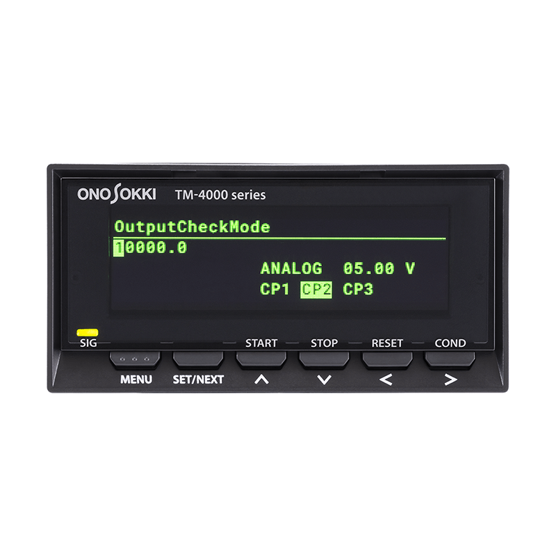
-

Main measurement screen -

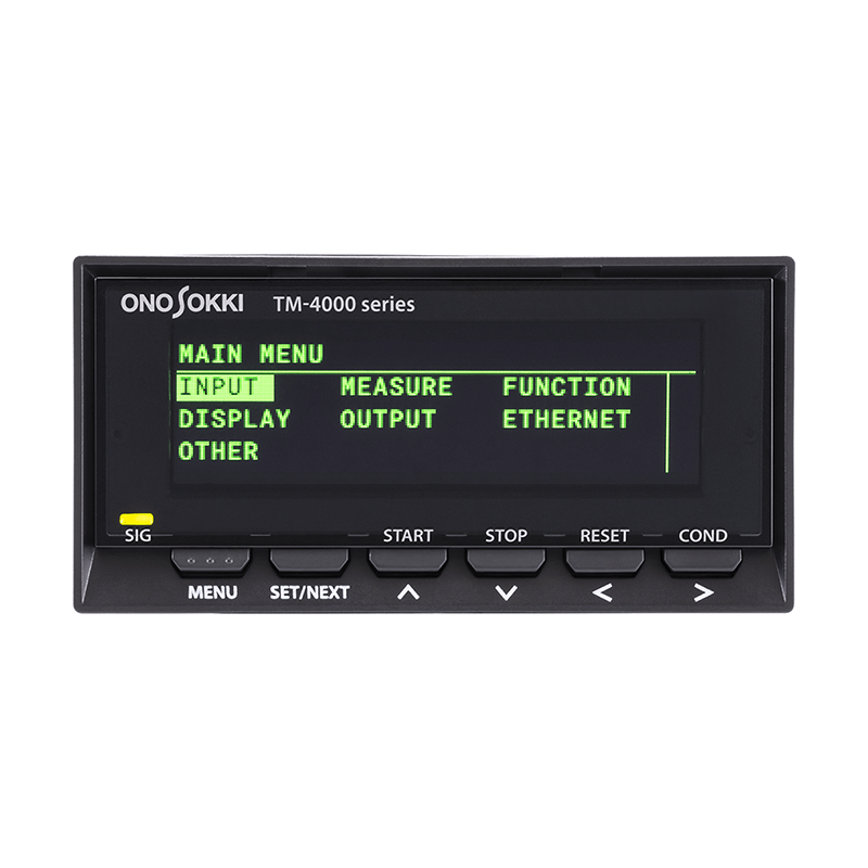
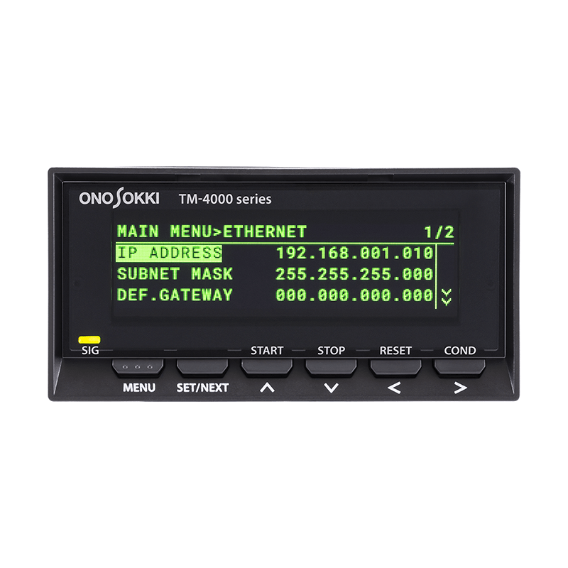
Settings screen

Ethernet compatible. Customizable to suit connected devices.
It can be customized to suit the external devices being connected. Various functions such as analog output, comparator output, and DC power supply can be combined.
Our external communication capabilities include Ethernet*, supporting the construction of factory networks.
*Optional features

Improved noise immunity signal input low-pass filter
To improve noise immunity, a 100 Hz filter has been added to the low-pass filter of the input signal. It can be selected from OFF / 100 Hz / 20 kHz.
(Standard equipment on all models)

In the case of a pulse input of 1P/R
Expanded setting range; Auto-zero function.
The setting range for the auto-zero function has been expanded to 0.0 (OFF) to 20.0 s.
It is now possible to set intervals of 0.5 seconds.
(Standard feature on TM-4100 and TM-4200 series)

The rapid deceleration tracking function has been completely revamped.
The rapid deceleration tracking function has been improved. During the time when the measured value becomes zero within the set time for auto-zero,
The function now includes deceleration calculations or the ability to retain measured values every 1 ms.
(Standard feature on TM-4100 and TM-4200 series)
-
STEP 1
Select basic specificationsRotation 1ch input Rotation 2ch input Reversible counter Passing time/passing speed TM-4100 TM-4200 TM-4300 TM-4400 -
STEP 2
Select the card to insert into the slot.
-
Each slot can accommodate one card.
-
Please ensure that cards are inserted into POWER and slot D.
-
The BCD output card can only be installed in the TM-4100.
POWER
power supplySlot A
Comparator outputSlot B
External communication functionSlot C
Analog outputSlot D
Input specificationsAC Power Card
TM-0400Comparator output card
TM-0440BCD output card
(Voltage output)
TM-0421Analog output card
(for TM-4100)
TM-04311-channel voltage input card
(for TM-4100)
TM-0405DC power card
TM-0401BCD output card
(Open collector output)
TM-0422Analog output card
(For TM-4200/4300/4400)
TM-04322-channel voltage input card
(For TM-4200/4300/4400)
TM-0406RS-232C communication card
TM-0450Line driver input card
(For TM-4200/4300)
TM-0407Ethernet communication card
TM-0460 -
-
STEP 3
Select software optionsCalculation function for TM-4100 Calculation function for TM-4300 TM-0470 TM-0480


-
【TM-4100/TM-4200】 Number of input channels 【TM-4100】1ch
[TM-4200] 2ch, 1ch (2 phase)Input format Voltage input or no-voltage input (open collector residual voltage less than 1 V) Input amplification format Select from AC/DC AC amplification section Sine wave input 0.2 ~ 30 Vrms Square wave input 0.6 ~ 42 Vp-p Input Frequency 1 Hz ~ 100 kHz DC amplification section Input signal Square wave with pulse width of 4 μs or more Input voltage range Hi:+4 ~ +30 V / Lo:–1 ~ +1 V Input Frequency 0.05 Hz ~ 100 kHz Time measurement 【TM-4100】 10 ms ~ 3600 s Input Impedance 10 kΩ or more Low-pass filter 【TM-4100】 Select from OFF/100 Hz/20 kHz
【TM-4200】 Select from OFF/100 Hz/20 kHz (common setting for ch-A/ch-B)Input connector 【TM-4100】 Terminal Block (D Slot SIG-COM1 Terminal)
【TM-4200】 Phoenix Contact Terminal Block (D-slot SIG-A-COM1 terminal / SIG-B-COM1 terminal)【TM-4300/TM-4400】 Number of input channels [TM-4300] 1ch (2 phase)
【TM-4400】2chInput format Voltage input or no-voltage input (open collector residual voltage less than 1 V) Input amplification format DC DC amplification section Input signal Square wave with a pulse width of 4 μs or more (when the low-pass filter is OFF) Input voltage range Hi:+4 ~ +30 V / Lo:–1 ~ +1 V Input Frequency DC ~ 100 kHz Input waveform [TM-4300] Square wave signal with 90° phase difference or single-phase square wave signal Duty 【TM-4300】 50±10 % Input Impedance 10 kΩ or more Low-pass filter Select from OFF/100 Hz/20 kHz (common setting for ch-A/ch-B) Input connector Phoenix Contact terminal block (D slot SIG-A-COM1 terminal / SIG-B-COM1 terminal) -
【TM-4100】 Arithmetic method Periodic calculation method Measurement accuracy Displayed value × (± 0.01%) ± 1 count (count value excluding decimal point) Measurement time Within 1 ms + 1 cycle time Auto-zero function If no input signal is detected for the specified time, the measured value will be set to zero.
- Select from 0.0 s (OFF) to 20.0 s (however, time measurement is possible up to 3600 s).
Rapid deceleration tracking function - When the function is ON: Deceleration calculation is performed while the measured value becomes zero within the set time for auto-zero.
- When the function is OFF: The measured value is set to zero after the auto-zero setting time, and the measured value is retained during that time.
Moving average function 1 ~ 1280 Start-stop interval measurement function Calculate the average, maximum, and minimum values from start to stop. Measurement items Select from: rotational speed / peripheral speed / moving speed / period / number of cycles / frequency / flow rate / transit time / arbitrary engineering units 【TM-4200】 Arithmetic method Periodic calculation method Measurement accuracy Single channel (ch-A or ch-B) Displayed value × (± 0.01%) ± 1 count (count value excluding decimal point) B/A or (BA)/A 2 × (single-channel measurement accuracy) B-A ±(ch-B measurement accuracy) ±(ch-A measurement accuracy) Measurement time Within 1 ms + 1 cycle time Auto-zero function If no input signal is detected for the specified time, the measured value will be set to zero.
- Select from 0.0 s (OFF) to 20.0 s
Rapid deceleration tracking function - When the function is ON: Deceleration calculation is performed while the measured value becomes zero within the set time for auto-zero.
- When the function is OFF: The measured value is set to zero after the auto-zero setting time, and the measured value is retained during that time.
Moving average function 1 ~ 1000 Start-stop interval measurement function Calculates the maximum value, minimum value, and average value over the most recent period from start to stop. Measurement items Select from rotational speed / peripheral speed / moving speed / frequency / arbitrary engineering units. 【TM-4300】 Counting range (internal counter) 0 ~ ±2,000,000,000 【TM-4400】 Measurable period 0.1 ms ~ 3600 s minimum resolution 1 μ s Measurement range 10 s/1000 s/3600 s Display accuracy Displayed value × (±0.05%) ± 1 count
*When measuring passage time -
【TM-4100/TM-4200】 Measurement condition preset function Up to four measurement settings can be saved and loaded for use. Pulse setting 1 ~ 999,999 P/R Rotating body diameter setting 0.1 ~ 99,999.9 mm pulse distance setting 0.1 ~ 99,999.9 mm Processing process length setting 【TM-4100】 0.1 ~ 99,999.9 mm Pulse factor 0.00001 × 10E-3 ~ 9.99999 × 10E+3 EU/Pulse 【TM-4300】 Measurement condition preset function Up to four measurement settings can be saved and loaded for use. Multiply × 1/ × 2/ × 4 Offset function 0 ~± 9,999,999 Counting direction switching function +/– Pulse factor 0.00001 × 10E-3 ~ 9.99999 × 10E+3 EU/Pulse 【TM-4400】 Measurement condition preset function Up to four measurement settings can be saved and loaded for use. Measurement Mode Single / Dual Measurement conditions Measurement conditions when the measurement mode is Single:
-
High level
-
Low level
-
Rising edge - between rising edges
-
Falling edge - Between falling edges
When the measurement mode is Dual:
-
Rising edge - between rising edges
-
Falling edge - Between falling edges
-
Between rising and falling edges
-
Between the falling edge and the rising edge
Measurement items Select from passing time / passing speed Distance measured between two points 0.1 mm ~ 99,999.9 mm Pre-scaling function
(Only when measuring passing speed)0.00001 × 10E-3 ~ 9.99999 × 10E+3 EU/Pulse -
-
【TM-4100】 Display OLED display Display update cycle 0.2 s/0.4 s/0.5 s/0.6 s/0.8 s/1.0 s to 10 s (in 1.0 s increments) Unit display Rotation and Speed r/s、r/min、r/h Circumferential speed mm/s、m/s、mm/min、m/min movement speed mm/s、m/s、mm/min、m/min、km/min、mm/h、m/h、km/h period s、min Number of times 1/s、1/min、1/h frequency Hz、kHz Flow Rate Measurement mL/s、mL/min、mL/h、L/s、L/min、L/h transit time s、min Arbitrary Engineering Units EU/s、EU/min、EU/h Number of display digits 6 digits Number of decimal places displayed Select from OFF/1/2/3 digits Number of zero-fixed display digits Select from OFF/1/2 digits SIG Indicator Flashes in sync with the input signal. Error message Backup memory error / Board error / Input frequency overload / Display digit overload Brightness switching Select from LO/MID/HI 【TM-4200】 Display OLED display Display update cycle 0.2 s/0.5 s/1 s Unit display Rotation and Speed r/s、r/min、r/h Circumferential speed mm/s、m/s、mm/min、m/min movement speed mm/s、m/s、mm/min、m/min、km/min、mm/h、m/h、km/h frequency Hz、kHz Arbitrary Engineering Units EU/s、EU/min、EU/h Number of display digits 6 digits + sign display Number of decimal places displayed Select from OFF/1/2/3/4/5 digits Number of zero-fixed display digits Select from OFF/1/2 digits SIG Indicator Flashes in sync with the input signal. Error message Backup memory error / Board error / Input frequency overload / Display digit overload Brightness switching Select from LO/MID/HI 【TM-4300】 Display OLED display Display update cycle 0.2 s/0.5 s/1 s Unit display OFF/mm/m/Count/s ([s] is displayed only when the TM-0480 calculation function is installed) Number of display digits 7 digits + sign display Number of decimal places displayed Select from OFF/1/2/3/4/5/6 digits SIG Indicator Flashes in sync with the input signal. Error message Backup memory error / Board error / Pulse count overload / Display digit overload Brightness switching Select from LO/MID/HI 【TM-4400】 Display OLED display Unit display Transit time (TIME): ms, s
Passing speed (P.SPEED): m/s, km/hNumber of display digits 6 digits Number of decimal places displayed Select from OFF/1/2/3 digits SIG Indicator Flashes in sync with the input signal. Error message Backup memory error / Board error / Display digit overflow / Time measurement range overflow Brightness switching Select from LO/MID/HI -
Output voltage Hi: +4.5 V or more / Lo: +0.5 V or less Output logic Negative logic Load resistance 100 kΩ or more -
Output voltage DC12 V ± 10 % Maximum Output Current 【TM-4100】 100 mA
[TM-4200/4400] 2ch total 180 mA
【TM-4300】 180 mA -
Equipment type Built-in type AC powered model Power supply rating 【TM-4100】 100 mA
[TM-4200/4400] 2ch total 180 mA
【TM-4300】 180 mAPower consumption TM-4110: 19 VA max
TM-4120: 21 VA max
TM-4130: 25 VA max
TM-4140: 21 VA max
TM-4100 Other configurations: 30 VA max
TM-4270: 27 VA max
TM-4370: 27 VA max
TM-4470: 27 VA max
TM-4200/4300/4400 Other configurations: 30 VA maxDC Powered Model Power supply rating DC12 V ~ 24 V ± 5 %、1.25 A max Power consumption TM-4111: 7 W max
TM-4121: 7 W max
TM-4131: 9 W max
TM-4141: 7 W max
TM-4100 Other configuration: 15 W max
TM-4200/4300/4400: 15 W maxsafety Overvoltage Category II Insulating properties Double insulation structure Insulation resistance Power supply +/- terminals (total) and FG terminal: 10 MΩ or more (DC 500 V) Usage environment Indoor use only Operating temperature/humidity 0 to 50°C / 30 to 80% RH (non-condensing) Storage temperature/humidity -10 to 60°C / 30 to 85% RH (non-condensing) Degree of contamination 2 Usage altitude 2000 m max Outline drawings 96 (W) × 48 (H) × 140 (D) mm or less

Weight Approximately 340 g (TM-4110)
Approximately 400 g (TM-4270/TM-4370/TM-4470) -
CE marking Low Voltage Command 2014/35/EU Standard EN 61010-1 EMC directive 2014/30/EU Standard EN 61326-1 RoHS Directive 2011/65/EU Standard EN IEC 63000 FCC/Canada FCC part 15B ICES-003(A)/NMB-003(A) This equipment has been tested and found to comply with the limits for a Class A digital device, pursuant to part 15 of the FCC Rules.
These limits are designed to provide reasonable protection against harmful interference when the equipment is operated in a commercial environment.
This equipment generates, uses, and can radiate radio frequency energy and, if not installed and used in accordance with the instruction manual,
may cause harmfulinterference to radio communications. Operation of this equipment in a residential area is likely to cause harmful interference in which case the user will be required to correct the interference at his own expense.
canada:CAN ICES-003(A) / NMB-003(A) -
TM-4100 Mounting brackets: 1 set (2 pieces)
Instruction manual (1 set)TM-4200/4300/4400 D-slot connector (Phoenix Contact FMC 1,5/10-ST-3,5 1952348) 1 piece
• It comes packaged already installed in the D slot.
Mounting brackets: 1 set (2 pieces)
Instruction manual (1 set)
-
【TM-0400】 Power supply rating AC100 V ~ 240 V ± 10 %、50/60 Hz Power consumption 30 VA max 【TM-0401】 Power supply rating DC12 V ~ 24 V ± 5 %、1.25 A max Power consumption 15 W max -
Voltage input specifications Similar to the signal input section. Connector 【TM-0405】 Terminal Block (D Slot SIG-COM1 Terminal)
【TM-0406】 Phoenix Contact Terminal Block (D-slot SIG-A-COM1 terminal / SIG-B-COM1 terminal) -
Line driver input specifications RS-422A compliant Connector FMC 1.5/10-ST-3.5 1952348 x 1 (manufactured by Phoenix Contact) (included with TM-0407) -
Output specifications
Output format 6-digit parallel output Output format 【TM-0421】 Internal pull-up at +5V
【TM-0422】 NPN Open Collector Output
Maximum sink current 32 mA max Output voltage withstand voltage 24 V max Output logic Orthodox logic Data update time Within 100 ms Operating mode
Normal mode Output is updated every 100 ms (print commands are continuously output approximately every 100 ms). Request mode The output is updated when a request signal is received.

Request signal input specifications
Input type Negative logic (pulse width 10 μs or more) Operating edge Standing down Input voltage Hi:+4.2 V ~ +5.25 V/Lo:0 ~ +0.9 V Pin number and signal name

BCD Pin Assignment
Pin signal Pin signal Pin signal 1 BCD output 1 × 10⁻⁶ 0 13 BCD output 1 × 10³ 25 Start input 2 2×10 0 14 2×10 3 26 Stop input 3 4×10 0 15 4×10 3 27 Reset input 4 8×10 0 16 8×10 3 28 NC 5 BCD output 1 × 10¹ 17 BCD output 1 × 10⁴ 29 NC 6 2×10 1 18 2×10 4 30 NC 7 4×10 1 19 4×10 4 31 NC 8 8×10 1 20 8×10 4 32 NC 9 BCD output 1 × 10² 21 BCD output 1 × 10⁵ 33 Data Request 10 2×10 2 22 2×10 5 34 NC 11 4×10 2 23 4×10 5 35 print command 12 8×10 2 24 8×10 5 36 GND -
【TM-0431】 Number of output channels 1ch Output Type Select from voltage/current Output method 16-bit D/A conversion method Output update time Choose from 1 ms/10 ms/20 ms/50 ms/100 ms/200 ms/500 ms/1 s Voltage output Output range Select from 0-10V/0-5V/1-5V Load resistance 100 kΩ or more Linear number ± 0.1 % FS Zero temperature drift ± 0.05 % FS/℃ Span temperature drift ± 0.05 % FS/℃ Current output Output range Select from 4-20 mA / 0-16 mA Load resistance 500 Ω or less Linear number ± 0.1 % of span Zero temperature drift ± 0.05 % of span/℃ Span temperature drift ± 0.05 % of span/℃ Output format terminal block 【TM-0432】 Number of output channels 1ch Output Type Voltage output Output method 16-bit D/A conversion method Output update time 1 ms Voltage output Output range ±10 V Load resistance 100 kΩ or more Linear number ± 0.1 % FS Zero temperature drift ± 0.05 % FS/℃ Span temperature drift ± 0.05 % FS/℃ Output format terminal block -
Contact output 1 Make contact output × 3 (COMP1/COMP2/COMP3)
- Individual judgment conditions can be set.Judgment conditions UPPER [TM-4100/4200/4400] 6-digit setting
【TM-4300】 7-digit setting
• When UPPER ≤ Main measurement value, the relay is turned ON.LOWER [TM-4100/4200/4400] 6-digit setting
【TM-4300】 7-digit setting
• When LOWER > Main measurement value, relay ONOK When all comparators set to UPPER or LOWER are OFF, the relay turns ON. ERROR ERROR: Relay ON when an error other than communication occurs. Contact operation mode Automatic recovery mode After the relay is turned ON, it will return to OFF when the judgment conditions are no longer met.
(Hysteresis can be set in the judgment conditions UPPER and LOWER, from 0 to 20%)Hold mode [TM-4100/4200/4300]
Once the relay is turned ON, it will remain ON even if the conditions for judgment are no longer met.Shot output mode If the relay ON condition is met, it will turn ON for the specified time and then return to OFF.
(Adjustable time: 10 to 2000 ms, in 10 ms increments)Output delay function [TM-4100/4200/4300]
The relay turns ON if the set value is exceeded for a set period of time or longer (configurable time: 0 to 1000 ms, in 10 ms increments).Reset function [TM-4100/4200/4300]
When in hold mode, the relay is returned to OFF.Maximum contact capacity DC:30 V/1 A AC:250 V/1 A Output update time Approximately 10ms Output format terminal block -

RS-232C communication specifications
Baud rate 9600 bps/19200 bps/115200 bps Data bits 8 bit parity Nothing Stop Bit 1 bit Flow control Hardware Terminator CR+LF -

Ethernet communication specifications
Electrical specifications IEEE 802.3 compliant Transmission method 10BASE-T / 100BASE-T automatic selection Communication protocol Socket communication using TCP/IP (IPv4) -
(Effective when a BCD output card, RS-232C communication card, or Ethernet communication card is installed.)
Gate function 【TM-4100/4200】 START/STOP/RESET
【TM-4300】 START・STOP/OFFSET/RESET
【TM-4400】 START/RESETWhen voltage is input Hi:+4.2 V ~ +5.25 V / Lo:0 ~ +0.9 V When there is no voltage input Open-circuit voltage: 5 V ± 0.25 V
Short-circuit current: 1 mA max
Contact resistance: 50 Ω or lessGate signal timing 
[TM-4300] START/STOP stops measurement while a Low level is input.
[TM-4400] START is in operation while a low level input is being used.
-

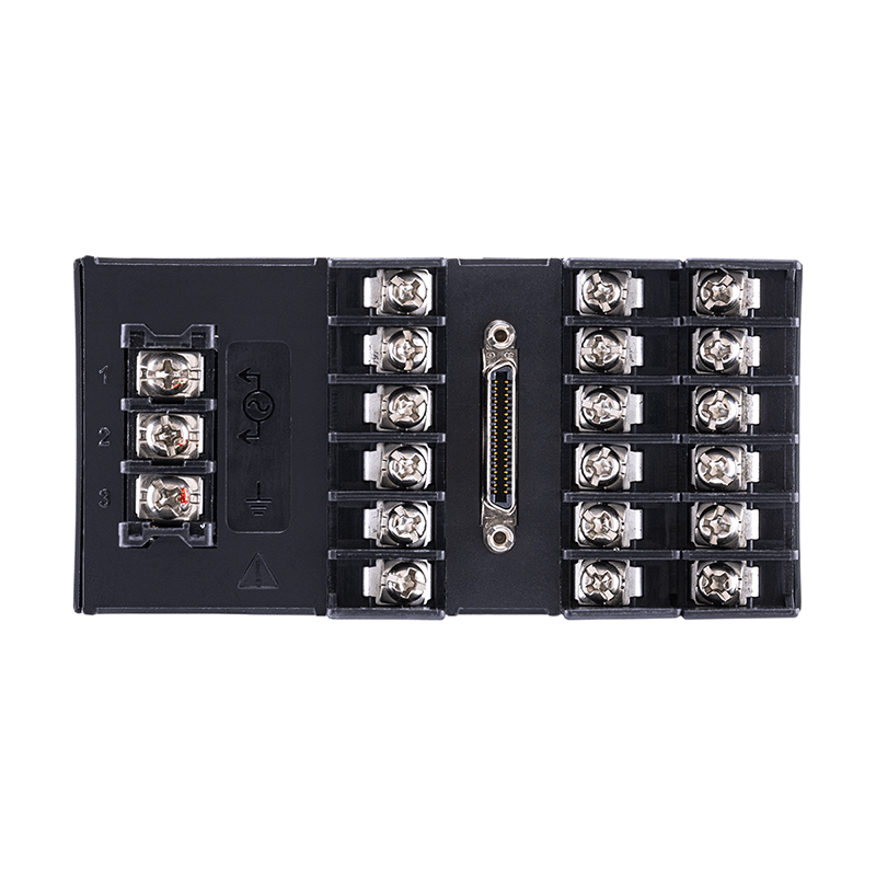
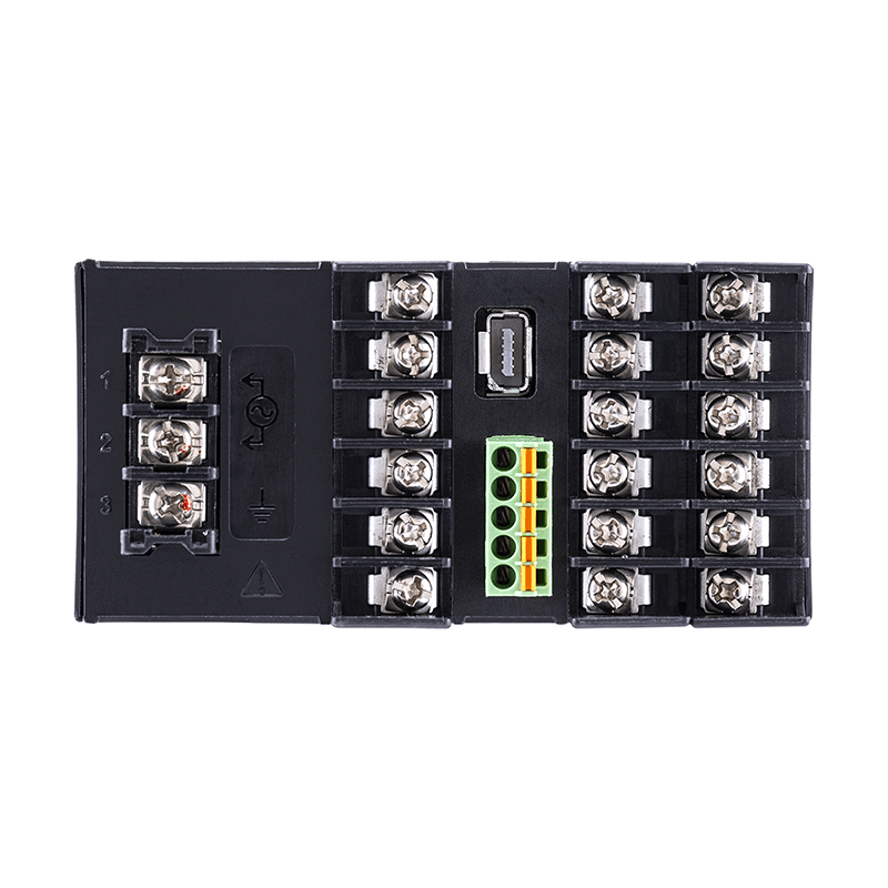
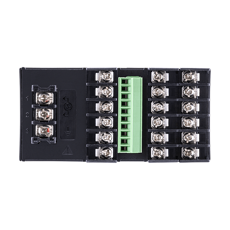
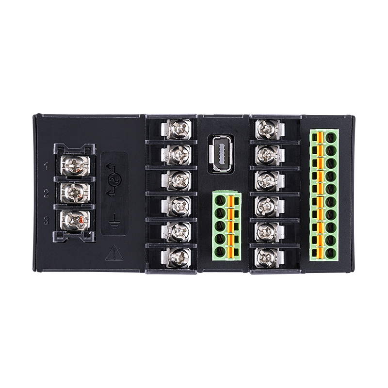
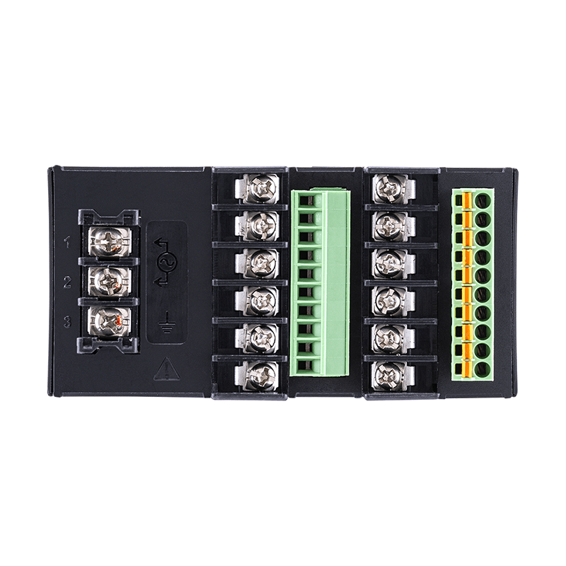
Terminal layout diagram (an example for the TM-4100 series)