

Torque Meter Frequently Asked Questions
Question number FAQ-1304
TS-2600 RS-232C command
I will explain RS-232C. For questions regarding parameter settings, please refer to the section "Configuration Procedure Document"; for information on N-0 settings, please refer to "How to Set N-0 Using Terminal Mode."
1. Overview
RS-232C is a serial communication interface standardized by the Electronic Industries Association (EIA). The RS-232C interface of this device enables data reading and writing of N-0 correction values through suitable programs on mini-computers or personal computers. If there is a computer that supports terminal emulation or VT-100 terminal emulation, it is possible to write the zero correction value/N-0 correction value in the terminal mode of this device.
2. Specifications
| Standard | EIA and JIS X5101 compliant |
|---|---|
| communication method | gait synchronization full duplex mode |
| Transmission Speed (Baud Rate) | 9600 bps |
| Character length | 8-bit |
| parity check | none |
| Stop bit length | 1 bit |
| X Parameter Control | XON - XOFF control |
| Terminator | CR + LF |
3. How to connect to the computer.
Cable wiring
If external devices use control signals, those control signals will be ignored in the cable wiring or in the program.
Cable Wiring Example
Compatible connector type (signal cable side): R03-PB3M (manufactured by Tajimi Wireless Co.)<sold separately>
Basic connection (when communicating using only TxD and RxD signal lines)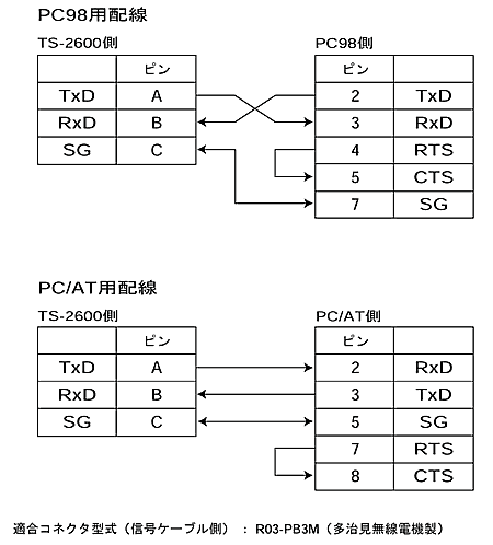
4. Explanation of Signals
| signal name | Function | Input and output |
|---|---|---|
| TxD(BA) | transmission data | Output |
| RxD(BB) | received data | input |
| RTS(CA) | send request | Output |
| CTS(CB) | Sendable | input |
| SG(AB) | Signal grounding | − |
(1) TxD (Transmit Data)
The transmit data output signal is usually in the MARK state (-9 V). +9 V level... 0 (SPACE)
-9 V level... 1 (MARK)
(2) RxD (Receive Data)
This is the input signal for the transmitted data.
+9 V level ... 0 (space)
-9 V level ... 1 (mark)
(3) SG (Signal Ground)
It is the common for signals.
5. Function
Writing
| zero correction value of torque | 1 point each for CW and CCW |
|---|---|
| N-0 correction value | 5 points each for CW and CCW. |
| Auto Zero | Zero correction setting |
■ Reading out
| torque measurement value | Average value of the measurement gate time set in parameter settings 1-7/1-8. |
|---|---|
| rotational measurement value | Average value of the measurement gate time set in parameter settings 1-7/1-8. |
| set value | Range factor, P/R, decimal point, torque zero correction value (CW/CCW), N-0 correction value (CW/CCW), rotation direction, parameter setting details. |
| signal situation | Torque signal input, rotation signal input, READY, trigger |
6. List of Commands
The command terminator uses CR (0DH) or LF (0AH), and output from the TS-2600 is appended with CR+LF. Output can be temporarily paused with Xoff (ˆS: 13H) and resumed with Xon (ˆQ: 11H).
Data reading
| RTD (Read Torque Data) | We will read the torque display value. |
|---|---|
| RRD (Read Revo Data) | Perform reading of the rotational display value. |
| RDD (Read Display Data) | The torque display value and rotation display value will be output separated by a comma. |
| RLO (Read Logging On) | The torque display value and rotation display value are separated by "," and are continuously output every gate time until the "RLF " command is received. |
| RLF (Read Logging off) | "Stops continuous output by the 'RLO' command." |
Writing of setting values.
Writing the settings cannot be performed unless the LOCK switch on the front panel is in the UNLOCK position.| STZn ,d (Set Torque Zero) | n = 0 : CW , 1 : CCW d = - 1 , 0 ~ 99999 Writes the zero correction value of torque. When d = - 1, it has the same function as the front panel TRQ ZERO switch. |
|---|---|
| STNn ,r(P1), t(P1), r(P2), t(P2), r(P3), t(P3), r(P4), t(P4), r(P5), t(P5), (Set Torque N-0) | n = 0: CW, 1: CCW r (P1 ~ P5) = 0 ~ 99999 (Rotation data for each point r/min) t (P1 ~ P5) = 0 ~ ±9999 (Torque data for each point) N-0 correction value will be written. If the data is valid, it will be sorted in ascending order of rotation values, and the N-0 table will be calculated. (The correction will be effective if the N-0 switch is ON.) |
| SBD (Set Backup Data) | Writing to the full backup memory will be performed. |
Reading of setting values
| RTF (Read Torque Factor) | Reading of the torque factor set value will be performed. | ||||||||||||||||
|---|---|---|---|---|---|---|---|---|---|---|---|---|---|---|---|---|---|
| RTR (Read Torque Range) | Reading the set value of the torque range. | ||||||||||||||||
| RTP (Read Torque decimal Point) | Reading the set value for the decimal point display of torque. | ||||||||||||||||
| RTZn (Read Torque Zero) | n = 0 : CW , 1 : CCW Reads the zero correction value of the torque. | ||||||||||||||||
| RTNn (Read Torque N-0) | n =0 :CW ,1 :CCW Reading of the correction values will be performed. Each data point is separated by a comma and will be output in the following order.
| ||||||||||||||||
| RRP (Read Revo Pulse) | Reading the rotation P/R setting value. | ||||||||||||||||
| RPS (Read Parameter Setting) | Reading the parameter setting values. Each data point is either '0' or '1', separated by commas, and will be output in the following order.
| ||||||||||||||||
| RMD (Read MoDe) | Reading out the action mode.
| ||||||||||||||||
| RCD (Read Condition Data) | We will read the condition data. Each data point is either '0' or '1', and they will be output in the following order, separated by commas.
| ||||||||||||||||
| RBD (Read Backup Data) | Perform a full backup memory read. | ||||||||||||||||
| VER (VERsion) | Reading the ROM version. |
For other tests
| STA (Set Torque Analog) | Writing torque output DA values (effective only in CALIBRATION mode) will be performed. |
|---|---|
| SRA (Set Revo Analog) | Writing the rotation output DA value (effective only in CALIBRATION mode) will be performed. |
| TRM (TeRMinal mode) | Entering terminal mode. |
Last updated: March 15, 2002