

Frequently Asked Questions about the Tachometer
Question number FAQ-0915
How to set up the analog output of TM-2130
By using a detection gear (with 60 teeth), you can obtain analog output corresponding to the rotational speed with the MP-981, MP-9100, and TM-2130. This document will explain the setup method. Please refer to a separate manual for settings related to the digital display.
|
Attention Ripple phenomenon (see Table 1)
|
-
The analog output is constructed with a separate circuit from the digital display, so it is not affected by settings related to the digital display.
-
The analog output terminals simultaneously output voltage (10V/frequency range) and current (4-20mA/0-frequency range), but there are conditions for using both voltage and current outputs at the same time.
-
For more details, please refer to the instruction manual.
Measurement Conditions
I will explain under the following measurement conditions.
- Number of teeth on the gear: 60 (60P/R)
- Rotary Detector: MP-981
- Measurement limit (full scale): 8000 r/min
Analog output settings
Selection of frequency range
We will find the maximum frequency of the input signal from the following equation.
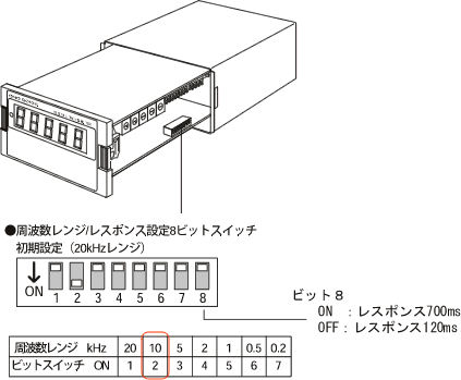
Set the frequency range '10kHz' to cover the maximum frequency.
Set "Bit 2: ON" and "Bits 1, 3, 4, 5, 6, 7: OFF" as shown in Figure 1. You can select from 7 frequency ranges: 20kHz, 10kHz, 5kHz, 2kHz, 1kHz, 500Hz, and 200Hz. The selected frequency range becomes F.S (full scale), and when the input signal matches the frequency of the selected range, a voltage output of 10V and a current output of 20mA will be produced.
(Example) When setting the 10kHz range
the voltage output will be 10V and the current output will be 20mA when the input signal is 10kHz. Note that the current output will be 4mA when there is no signal.
The digital display shows a value that has been corrected based on the multiplier setting. Therefore, please note that it is necessary to convert the voltage output to read the displayed value.
(3) Setting of the response
Set the response (responsiveness) with bit 8 in Figure 1. There are settings for 'bit 8: OFF (120ms)' and 'bit 8: ON (700ms)', which change the ripple. Please refer to the table below for the amount of ripple. When ON (response 700ms), the output is smoother compared to when OFF (response 120ms). If used in a low-frequency range or if an average output is desired, set 'bit 8: OFF (700ms)'.
Figure 1
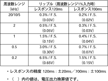
Table 1: Ripple
How to read the table
(Example) Ripple at a frequency range of 10kHz, response time of 120ms, and setting of 0.3%/F.S (0.03V).
Frequency range 1% = 10 kHz × 1% = 100 Hz
When the input signal is at 100Hz, there is a ripple of 0.03V (10V × 0.3% = 0.03V). The ripple becomes larger than 0.03V as the frequency decreases below 100Hz.
Specifications and Wiring of Analog Output
Analog Output Specifications
| frequency range | 20kHz、 10kHz、 5kHz、 2kHz、 1kHz、 0.5kHz、 0.2kHz |
|---|---|
| linearity | ±0.3% / full scale |
| output voltage | 0 to 10V (load of 1kΩ or more) for each frequency range. |
| output current | For each frequency range, 4-20mA (load under 500Ω) *When the voltage load is over 100kΩ, simultaneous output of voltage and current is possible. |
| output ripple | It varies depending on the frequency range and response. |
| output adjustment | Approximately ±5%/full scale (voltage), approximately ±3%/full scale (current) |
| zero setting accuracy | ±0.5%/full scale (voltage output, room temperature), ±0.3%/full scale (current output, room temperature) |
| Zero Drift | ±0.01%/full scale/°C |
| spandrift | ±0.025%/full scale/°C |
| Response | Switching between 120ms±20ms or 700ms±100ms |
Wiring Method (4-2)
The wiring should be done as shown in Figure 2. Use shielded cables, and please ground the shield at the connection point.
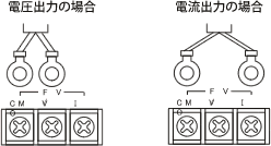
Figure 2
(4-3) When using voltage output and current output simultaneously
When connecting voltage output and current output simultaneously, the input resistance of the connection point must meet the conditions specified in Figure 3.
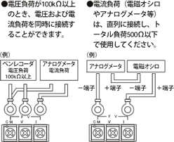
Figure 3
Last updated date: 2009-07-21