

Frequently Asked Questions about the Tachometer
Question Number FAQ-0908
BCD Output and Positive/Negative Logic
Logical expressions and truth tables
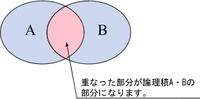
Logic is a field of study that attempts to explain things in a systematic and reasoned manner, and one of its branches is logical algebra (Boolean algebra). In logical algebra, all phenomena are divided into two categories—true and false—and the essence of things is considered through their combinations. The phenomena subject to being true or false are called variables and are represented by letters such as A, B, and C. Furthermore, the values these variables take—true and false—are represented by 1 and 0, respectively. Combinations of logical variables are called logical expressions, and there are three types of basic functions used to create these expressions: logical product (AND operation), logical sum (OR operation), and negation. You may have heard terms like 'taking the AND' or 'taking the OR,' which refer to these logical expressions. A table that represents the variables of a logical expression and their results in the form of 1s and 0s is called a truth table. To explain a truth table using the example of a logical product: when variables A and B exist in a certain domain, and an element is 'A and (AND) B,' that element is said to be the 'logical product of A and B.'
Table 1: Truth Table of Logical Sum
| A | B | A・B |
|---|---|---|
| 1 | 1 | 1 |
| 1 | 0 | 0 |
| 0 | 1 | 0 |
| 0 | 0 | 0 |
(Note) When both A and B are true, A·B is 1; for all other combinations, it is 0.
Logic Expressions and Positive/Negative Logic in Digital IC Circuits
In digital IC circuits, a single signal or signal line is considered to be at H level (High Level, hereafter referred to as H) at 5 V, for example, and at L level (Low Level, hereafter referred to as L) at 0 V. In other words, since a single signal (variable) is output as either the H or L level, it can be understood by assigning, for example, 1 (true) to H and 0 (false) to L. Representing the previous Table 1 using the signal levels of a digital IC circuit results in Table 2 and Table 3.
Table 2: Truth Table for AND Circuit (Positive Logic)
| A | B | A・B |
|---|---|---|
| H | H | H |
| H | L | L |
| L | H | L |
| L | L | L |
<Table 3> Truth Table for an AND Circuit (Negative Logic)
| A | B | A・B |
|---|---|---|
| L | L | L |
| L | H | H |
| H | L | H |
| H | H | H |
When H is taken as 1 (true) and L as 0 (false) as shown in Table 2, it is called 'positive logic'; conversely, when L is taken as 1 (true) and H as 0 (false) as shown in Table 3, it is called 'negative logic'.
Positive Logic, Negative Logic, and BCD Output
The BCD output signal represents decimal numbers from 0 to 9 using a combination of H and L on four signal lines, known as Binary Coded Decimal (BCD). Each of the four lines is assigned to a binary digit, starting from the lowest digit as 2 0 (=1), 2 1 (=2), 2 2 (=4), and 2 3 (=8). This is why they are commonly referred to as 1, 2, 4, and 8. For example, a value represented as 1001 in binary becomes 1×2 3 + 0×2 2 + 0×2 1 + 1×2 0 = 9 in decimal. The truth table for BCD codes is shown in Table 4.
Table 4: BCD Code (Binary Decimal) Truth Table
| Decimal | Stage 2 | Decimal | ||
|---|---|---|---|---|
| 1st digit (2 3) | 1st digit (2 2) | 1st digit (2 1) | 1st digit (2 0) | |
| 0 | 0 | 0 | 0 | 0 |
| 1 | 0 | 0 | 0 | 1 |
| 2 | 0 | 0 | 1 | 0 |
| 3 | 0 | 0 | 1 | 1 |
| 4 | 0 | 1 | 0 | 0 |
| 5 | 0 | 1 | 0 | 1 |
| 6 | 0 | 1 | 1 | 0 |
| 7 | 0 | 1 | 1 | 1 |
| 8 | 1 | 0 | 0 | 0 |
| 9 | 1 | 0 | 0 | 1 |
Note: While the binary combination 1111 is possible, in Binary Coded Decimal (BCD), values greater than 9 do not exist and will result in an error (though some systems assign values above 9 to characters such as A, B, ... F).
Since Table 4 represents a single digit, representing 4 decimal digits in BCD would require 4 digits × 4 signals = 16 signals (signal lines).
When looking at catalog specifications for BCD output, you will see notations for positive logic and negative logic. When positive logic is specified, a true value is represented as H (high level, e.g., 5 V), as described in section (2) above. Conversely, when negative logic is specified, it indicates that a true value is output as L (low level, e.g., 0 V). Additionally, open-collector output circuits are sometimes used in BCD output circuits. In an open collector, a transistor is used in the final output stage, and because this transistor either operates (ON) or does not (OFF), the terms 'on' and 'off' are sometimes used, where 'on' corresponds to L and 'off' corresponds to H. Therefore, with open collectors, it is necessary to exchange signals while paying close attention to the relationship between on (L)/off (H) and positive/negative logic.
The following table shows the truth table for a 5-digit BCD code with open-collector negative logic outputs, represented as ON (ON display) and OFF (-- display). Please use it for your reference.
Conversion of BCD Output
Please enter the displayed value in the lower text box as a half-width number, ignoring the decimal point, and press the [Convert] button.
The bits will appear in the table below.
For re-entry, please press the [Reset] button and then input.
Last updated date: 2009-07-21