

Digital Gauge Frequently Asked Questions
Question number FAQ-0115
Connection between GS/BS series sensor and RV-3150 reversible counter.
This document describes the wiring for connecting the GS/BS series sensor to the RV-3150 reversible counter, as well as the setup procedure on the RV-3150 side. Please have the RV-3150 manual ready.
1. Wiring Diagram
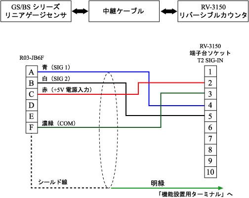
<Relay Cable Wiring Diagram>
The relay cable is available as an option.
2. Sensor input channel setting (factory setting 0 P-IN)
The signals from the GS/BS series are square wave (voltage) output signals, so in the RV-3150's "parameter setting function," you will configure the sensor input channel as follows.
SENSOR CH SET |
3. Sensor type setting (factory setting 0 DUAL)
- The signal of the GS/BS series is a two-phase square wave (voltage) output signal, so in the sensor type setting of the RV-3150's "parameter setting function," it should be configured as described below.
SENSOR TYPE SET |
4. Multiplication setting (default at shipment 2 * 4)
- When connecting to the GS/BS series, set the multiplication factor to 4 in the 'parameter setting function' of the RV-3150 as shown below.
PULSE MULT SET |
5. Counting method setting (at the time of shipment 0 (+))
- When counting the push of the spindle from the GS/BS series as a positive (+) count, set the counting direction in the "parameter setting function" of the RV-3150 as follows.
SENSOR DIR SET |
6. Decimal point position setting (Factory setting 0 OFF)
- When connecting to the GS/BS series, set the decimal point position in the 'parameter setting function' of the RV-3150 as follows.
In the case of a resolution of 1 μm
D.POINT SET |
<Resolution of 10 μm>
D.POINT SET |
7. Analog output full scale setting (factory setting FS → 999999)
- When connecting to the GS/BS series, set the count value corresponding to the full-scale value of the analog voltage output (F.S. value: 10 V) in the "parameter setting function" of the RV-3150.
<If you want to set the full-scale value to 30 mm (measurement unit: 1 μm)>
ANALOG FS SET |
<If you want to set the full scale value to 30 mm (measurement unit: 10 μm)>
ANALOG FS SET |
| Output update time | within 15 ms |
|---|---|
| Resolution | 12-bit D/A method Stroke 50 mm Type 1μm unit: 25 μm = 5 mV output |
| linear error | ±0.3 %/F.S. |
8. calibration Signal output settings
- When calibrating the output voltage, set it as follows. After calibration is complete, be sure to return to 0: ZERO.
If you want to output a full-scale value at 10 V.
CAL SET |
9. Refer to the RV-3150 manual for the following settings as necessary.
- Index Setting
- Comparator Condition Setting
- Offset value setting
- LCD upper/lower section display item settings
- Ratio calculation function ON/OFF
- BCD Output Logic Settings
- RS-232C baud rate setting
- LCD backlight lighting method setting
Last updated: 2001-01-12