

Digital Gauge Frequently Asked Questions
Question number FAQ-0098
AA-6100/6101 Air Lifter Operating Instructions
This product is a dedicated air lifter for GS-1513, 1513A, 1530, 1530A, 1613, 1613A, 1630, and 1630A.
suitable linear gauge
| Air Lifter Type | suitable for linear gauge sensor |
|---|---|
AA-6100  |
GS-1513A (discontinued), GS-1613A (discontinued) GS-1513 (discontinued), GS-1613 (discontinued) |
| AA-6101 |
GS-1530A (discontinued), GS-1630A (discontinued) GS-1530 (discontinued), GS-1630 (discontinued) |
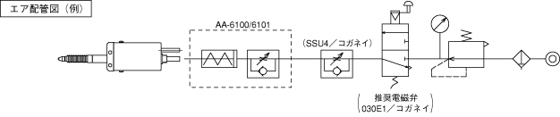
Air piping diagram
A basic example of air piping is shown in the figure below. Please provide all parts except for those indicated by the dotted line.
Installation Method
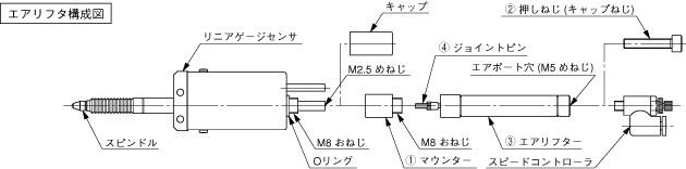
Below is the installation diagram for the GS sensor of the air lifter.
*When using tools, be careful not to overtighten the screw section.
*Please use adhesive for preventing loosening on the screw section.
- Remove the cap from the linear gauge sensor. Please leave the O-ring inside the cap on the sensor side.
- Screw in the <(1) mount> into the section where the cap has been removed to secure it.
- Screw the <(2) push screw (cap screw)> into the airport hole of the <(3) air lifter> (M5 female thread) to push out the <(4) joint pin>.
- Push the spindle of the linear gauge sensor and screw in the joint pin (4) into the female screw (M 2.5) at the top of the spindle. While it can be screwed in by hand, it is recommended to use tools. Please be careful not to apply too much adhesive to the joint pin (4), as it may affect the movement of the sensor.
- Screw the air lifter into the screw part of the mount (M8 male thread). Please be careful not to over-tighten, as this may impair the movement of the spindle.
- Slowly remove the push screw (cap screw).
- Fix the attached speed controller to the air port hole (M5 female thread) of the air lifter.
- Once the above installation is complete, the spindle of the linear gauge sensor will be in a contracted state. When air is supplied from the speed controller, the spindle will return to its original length due to the force of the spring built into the linear gauge sensor.
(The pressing force of the spindle will be the same as the catalog value)
Driving Precautions
When supplying air.
- Please adjust the spindle's operating speed with the speed controller.
If it is too fast, it may damage the object being measured. Also, if the spindle exceeds the maximum response speed of the GS sensor, the counter will display an error. (The digital display will blink) - Please use the air filter to supply clean air.
Other
- When adjusting the return speed of the spindle, please install the exhaust throttle valve (SSU4 from Koganei) as close as possible to the speed controller to regulate the movement.
- Please ensure that water or oil does not directly splash into the hole located in the center of the air lifter.
(The air lifter is not subject to IP64.) - Using a large amount of adhesive to prevent loosening may cause it to enter the bearing and lead to operational failures. Please be careful about the amount of adhesive used and the areas where it is applied.
- Due to the structure of the air cylinder, after a long period of inactivity or in cold environments, there may be a poor response time from the solenoid valve after it is turned ON before it operates. Additionally, when it starts moving, it may suddenly pop out, which could lead to a lack of speed control. Therefore, please conduct a trial run before measurements.
Specification
| range of motion | AA-6100:0~13 mm AA-6101:0~30 mm |
|---|---|
| Use fluid | air |
| Use pressure | 0.25~0.7 MPa |
| guaranteed pressure resistance | 0.9 MPa |
| Operating Temperature Range | 0 to +40 degrees Celsius |
| Storage Temperature Range | -10 to +55 °C |
| Weight | AA-6100: 40 g AA-6101: 50 g Includes speed controller |
| lifespan | 5 million times |
| Accessories | Mount, speed controller (Koganei SS4-M5B), push screw |
Last updated: 2001-01-12