

Digital Gauge Frequently Asked Questions
Question number FAQ-0071
Measurement Procedure and Release of Error Messages
Measurement
Connect to peripheral devices.
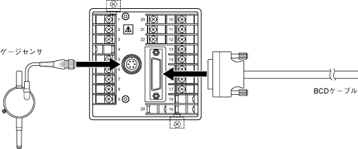
Power will be turned on. This device will immediately enter operational status.
Move the spindle of the gauge sensor and confirm that the values on the front panel display change.
Move the gauge sensor's spindle to the position you want to set to zero point and stabilize the spindle.
Reset the measurement value to zero at the zero point position using one of the following methods.
- Press the RESET switch on the front panel.
- Short-circuit the RESET input terminal (No.21) and the COM terminal (No.22) on the back panel.
- Input a low-level voltage signal from the reset input (pin 32) of the BCD OUT connector on the back panel.
Set the judgment value of the front panel to the preset switch.
Entering measurement. As the movement amount of the gauge sensor's spindle is displayed on the display section, a judgment is made.
Hold of measurement values
You can hold the display section and BCD output. There are two methods to do this.
- Short-circuit the back panel HOLD input terminal (No. 22) and COM terminal (No. 23).
- Input a low-level voltage signal from the hold input (pin 31) of the BCD OUT connector on the back panel.
Stopping the judgment output.
By inputting the preset gate signal in the following manner, the judgment will be forcefully presented, and the judgment output will be turned OFF.
- Short-circuit the input terminals for preset gates 1 to 4 (No. 5 to No. 8) and the COM terminal (No. 9) on the rear panel terminal block.
Release of error message
In the event of a miscount in this counting circuit, the display will blink, and the error output (pin 30) of the BCD OUT connector will be activated. The error state can be cleared by the following method.
- Press the RESET switch on the front panel.
- Short-circuit the RESET input terminal (No.21) and the COM terminal (No.22) on the back panel.
- Input a low-level voltage signal from the reset input (pin 32) of the BCD OUT connector on the back panel.
Please refer to DG-4000 Series Troubleshooting.
Last updated: 2000-12-08