

Vibration Comparator Frequently Asked Questions
Question number FAQ-1401
How to determine vibration levels as OK, UPPER, or LOWER using the VC-2100?
For the determination of vibration levels, the measurement conditions for band A and band B (such as bandpass filters) are set the same, with the judgment level for band A set to 'UPPER' and for band B set to 'LOWER'. With this setting, both will output an NG judgment if the measured values are greater than or equal to the set values. The PLC (Programmable Logic Controller) will determine the status as 'UPPER', 'LOWER', or 'OK' based on the combinations of NG outputs from bands A and B.
Measurement Judgment Timing Chart - Example
An example of specifying measurement time with GATE signal (AUTO) and determining PEAKHOLD is shown below. The NG judgment for band A and band B is set to "Hi" (measured value ≧ set value).
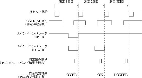
| Judgement | A band | B band |
|---|---|---|
| OVER | NG output | NG output |
| OK | (OK output) | NG output |
| LOWER | (OK output) | (OK output) |
Operation Procedure
-
Input the reset signal and clear the previous measurement values and judgment results.
-
Start the operation of the test sample, and when stable, input the GATE signal(AUTO)and perform the measurement.
-
After the measurement time has elapsed (with the GATE turned off), read the comparator outputs (judgment results) for the A band and B band.
-
The comparison results of Band A and Band B are incorporated into a PLC (Programmable Logic Controller), and an overall judgment of 'UPPER', 'LOWER', or 'OK' is made.
-
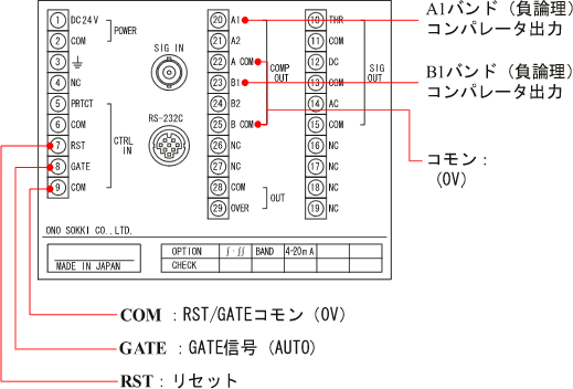
The reset signal, GATE signal (AUTO) operates when at a LOW level (0V).
-
The comparator output of band A and band B is an open collector output (DC 30V, 25mA). In this example, negative logic is used.
Rear terminal block
The next diagram shows the rear terminal diagram. Please refer to the manual for signal specifications and wiring instructions to ensure correct wiring.
Measurement Mode
The VC-2100 measurement modes include 4 types: RMS / PEAK / MAX HOLD / PEAKHOLD. When you set the bandpass filter frequency, measurements are taken from the signal after passing through the bandpass filter. Measurement conditions are set for each A and B band. When using the "AUTO GATE" function, the measurement mode will be set to either "MAX HOLD" or "PEAKHOLD." For details on each, please refer to this "VC-2100 Measurement Modes and Compare Function".
Setting Operation
We will conduct a test and finalize the measurement conditions. For the setup method of VC2-100, please refer to this simple operation manual.
Last updated: January 19, 2009