

Vibration Comparator Frequently Asked Questions
Question number FAQ-1395
Comparator output and terminal block (reset, gate input)
For the compare function, please refer to the 'Measurement Mode and Compare Function', and for the setting operations, please refer to the 'Simple Operation Manual'.
To connect with external devices such as sequencers and control the judgment timing, perform AUTO operation. Control is done using reset signals and gate signals. For more details, please refer to the manual.
■ Reset signal, gate signal input
| input signal | Back terminal block No. | Specifications | Operation during AUTO driving. |
|---|---|---|---|
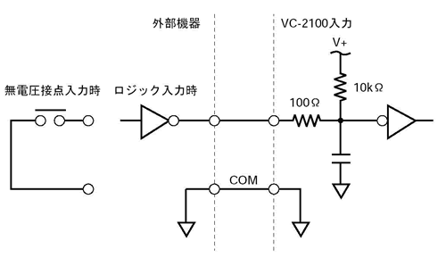
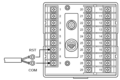
| Reset | No.7 Reset Signal No.9 COM | Short-circuit between terminals or perform a reset operation with a LOW level signal input. In the case of voltage signal input LOW: Below 0.8V | Reset the input when the gate is OFF (stop compare rate). (2) Gate ON (Comparison Start) Reading the judgment output with the gate OFF. (4) Return to (1) and proceed to the next measurement. |
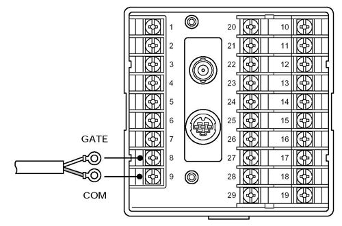
| gate | No.8 gate signal No.9 COM |
input circuit
terminal block
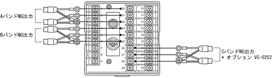
■Comparator output (NG signal)
A BAND, B BAND, and C BAND (optional) each output an NG (No Good) judgment signal.
| band | Rear output terminal block No. | |
|---|---|---|
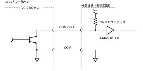
| A BAND NG Output | No.20 NG negative logic output No.21 NG positive logic output No.22 Same as above COM terminal | Open collector DC 35 V max, 25 mA max (Refer to the circuit diagram below) |
| B BAND NG Output | No.23 NG negative logic output No.24 NG positive logic output No.25 Same as above COM terminal | |
| C BAND NG output (optional) | No.26 NG negative logic output No.27 NG positive logic output No.28 Same as above COM terminal |
input circuit
terminal block
Last updated: July 15, 2002