Due to the frequency characteristics of the detector, torque measurements may appear even when the axis is rotating in an unloaded state. These values are reproducible, so by setting correction values for each rotation speed, it is possible to achieve high-precision measurements.
<Attention> Separate correction values need to be obtained and input for both CW and CCW. The correction for the selected direction can be made using the CW/CCW switch on the front panel. Please check the rotation direction settings first. |
How to obtain the N-0 correction value.
Set the detection axis to a no-load condition (with nothing attached to one side of the axis) and rotate it using a motor or similar device.Change the rotation speed within the range of speeds used and record the torque display values at each speed.
Please use the table below that lists the rotation speeds within the measurement range.| Rotational speed (r/min) | 0 | 1000 | 2000 | 3000 | 4000 | 5000 |
|---|
| Torque Count | | | | | | |
|---|
| Note 1 | In the count field, enter the number ignoring the decimal point.
Example: 1.234→1234, −0.20→−20 |
| Note 2 | Count refers to the number obtained by ignoring the decimal point of the value displayed as torque. |
This device can input 5 points. It approximates the input points linearly and also makes corrections for points outside the input range. It is possible to record with finer intervals in areas where there are large changes in numbers and coarser intervals in areas with small changes.
Example: Rotational speed → 200, 500, 1000, 2000, 5000
How to input the N-0 correction value
<Attention> Please set the correction values in ascending order starting from the lower rotation speeds.Please enter the count value ignoring the decimal point for the torque value.The torque value cannot exceed the torque capacity.The rotational speed input can accept values up to 99,999 r/min, regardless of the rotational speed capacity settings. |
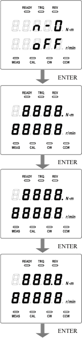 | - From the initial display of torque N-0 correction, pressing the right arrow key allows for the input of correction values.
- Input is possible using the right arrow key from the display of ON and CLR.
- If there are previous input values, overwriting is possible.
- The upper row shows torque values, and the lower row shows rotational speed.
It is possible to input the torque correction value for the first point, and the first decimal point lights up to indicate that it is the first point. - The LED in the input area is blinking.
- Move the input position (digit) with the right arrow key.
- Change the setting value with the up arrow key: the minus sign can be displayed using the MENU key.
- Confirm with the ENTER key, move to the next item.
It is possible to input the rotation speed of the first point. - The method of operation is the same as the input of the torque correction value at the first point. The explanation of the operation will be omitted below.
Input for the torque correction value at the second point is possible
The second decimal point indicating it is the second point lights up - The method of operation is the same as the input of the torque correction value at the first point. The explanation of the operation will be omitted below.
|
 | Input of the torque correction value for the third point is possible
The third digit indicating that it is the third point lights up - The method of operation is the same as the input of the torque correction value at the first point. The explanation of the operation will be omitted below.
It is possible to input the rotation speed of the third point. - The method of operation is the same as the input of the torque correction value at the first point. The explanation of the operation will be omitted below.
Input of the torque correction value for the 4th point is possible
The 4th decimal point indicating that it is the 4th point is lit up - The method of operation is the same as the input of the torque correction value at the first point. The explanation of the operation will be omitted below.
Input for the rotation speed of point 4 is possible. - The method of operation is the same as the input of the torque correction value at the first point. The explanation of the operation will be omitted below.
|
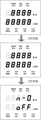 | Input of the rotation speed for point 5 is possible. - The method of operation is the same as the input of the torque correction value at the first point. The explanation of the operation will be omitted below.
After pressing the ENTER key on the input display for the rotation count at the 5th point, it returns to the initial display of N-0 correction. |
Enable N-0 correction.
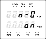 | - Pressing the up arrow key toggles between OFF, ON, and CLR in that order.
- Set to ON, confirm with the ENTER key, and move to the next item.
|

