

Torque Meter Frequently Asked Questions
Question number FAQ-1333
Method for external switching of rotation direction (CW/CCW) for TS-2700
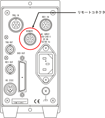
It is possible to input control signals from an external source using the REMOTE connector on the back panel. However, the cable connected to the REMOTE connector should be no longer than 5 meters, and shielding should be applied as necessary.
■ Operating Instructions
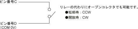
(1) Wire the REMOTE connector on the back panel (the cable side connector is included as standard) between pin numbers "C" and "D"
with a voltage-free contact output.
Suitable connector (signal code side): R03-PB8M (manufactured by Tajimi Wireless Electric) <standard included>
| ● REMOTE connector pin arrangement |
| pin | Signal Name | Remarks |
|---|---|---|
| A | CLR IN | Voltage-free contact input (Common is shared) |
| B | TRG IN | |
| C | CW/CCW switch | |
| D | COM | |
| E | READY OUT | Voltage-free contact output (Commons are separate) |
| F | Same as above COM1 | |
| G | TRG OUT | |
| H | Same as above COM2 |
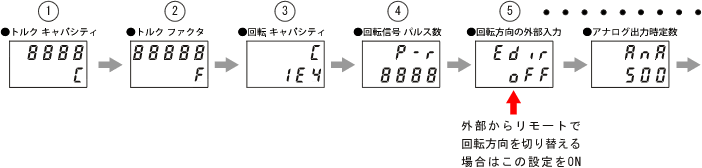
(2) Set the MENU to turn ON "External Input for Rotation Direction." This enables the CW/CCW switching from the REMOTE connector.
Press the MENU key for more than 2 seconds to enter settings mode.
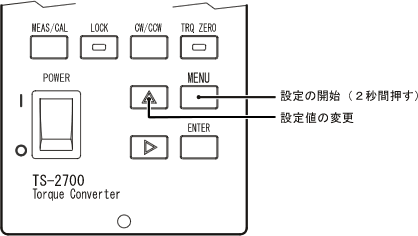
Use the -2 ENTER key to switch to "5. External Input for Rotation Direction" mode and turn the setting ON.
The ENTER key confirms the setting each time it is pressed and moves to the next mode.
Attention
When the rotation direction of the measurement axis is changed, the torque zero correction value and N-0 correction value will change. To use the device by switching the rotation direction, it is necessary to set the torque zero correction value and N-0 correction value for both CW and CCW directions. Once set, the torque zero correction value and N-0 correction value are stored in backup memory. During measurement, please switch the rotation direction of the attached motor and the CW/CCW setting of this device.
Last updated date: 2008-06-23