

Torque Meter Frequently Asked Questions
Question number FAQ-1297
Names and Functions of Each Part of TS-2100
1. Front panel
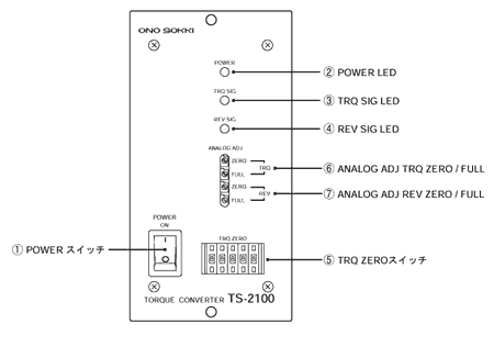
(1) POWER Switch
This is the main power switch of the device. Pressing the upper side of the switch turns the power on.
(2) POWER LED
The green LED lights up when the main power is supplied.
(3) TRQ LED
The green LED lights up when measurement signals SIG1/SIG2 from the torque detector are both input.
(4) REV LED
The green LED lights up when signals from the rotation detector, such as MP-981, are input.
(5) TQR ZERO Switch
This is a digital switch for setting the zero value of torque.
(6) ANALOG ADJ TRQ ZERO / FULL
This potentiometer is used to adjust the calibration of the analog output for torque data.
(7) ANALOG ADJ REV ZERO / FULL
This potentiometer is used to adjust the calibration of the analog output for rotation data.
2. Back Panel
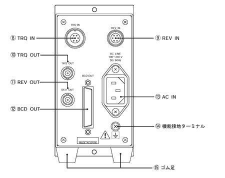
(8) TRQ IN
This is the connector for inputting signals from the torque detector.
Compatible connector: TRC116- 12A10- 7M10.5 (made in Tajimi)
Please be sure to use the dedicated cable included with the detector.
| Pin | signal name |
|---|---|
| A | SIG1 |
| B | SIG2 |
| C | SIG1 COM |
| D | SIG2 COM |
| E | NC |
| F | SIG COM |
| G | NC |
(9) REV IN
This is the connector for inputting signals from the rotation detector. Compatible connector: R03- PB6M (made in Tajimi)
Please use the dedicated rotation detector (MP-981 type electromagnetic detector) and the dedicated cable (MX-8105 5 m).
| Pin | signal name |
|---|---|
| A | SIG |
| B | NC |
| C | 12 V |
| D | FG |
| E | SIG COM |
| F | 12 V COM |
(10) TRQ OUT
This is the connector for the analog voltage output of the torque data. Compatible connector: C02 type (BNC) connector
(11) REV OUT
This is the connector for the analog voltage output of the rotation data. Compatible connector: C02 type (BNC) connector
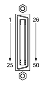
(12) BCD OUT
This is the connector for the BCD output of the torque/rotation data. Data and polarity are positive logic, hold, busy, print command are negative logic, all open collector output.
Compatible plug: DX40 - 50P (Hirose Electric), plug cover: DX - 50 - CV1 (Hirose Electric)
Signal cables are made to order.
| PIN number | signal name | PIN number | signal name | ||
|---|---|---|---|---|---|
| 1 | Data Output | 1×100 | 26 | Data Output | 2×101 |
| 2 | (Torque section) | 2×100 | 27 | (rotating part) | 4×101 |
| 3 | 4×100 | 28 | 8×101 | ||
| 4 | 8×100 | 29 | 1×10² | ||
| 5 | 1×101 | 30 | 2×10² | ||
| 6 | 2×101 | 31 | 4×10² | ||
| 7 | 4×101 | 32 | 8×10² | ||
| 8 | 8×101 | 33 | 1×10³ | ||
| 9 | 1×10² | 34 | 2×10³ | ||
| 10 | 2×10² | 35 | 4×10³ | ||
| 11 | 4×10² | 36 | 8×10³ | ||
| 12 | 8×10² | 37 | NC | ||
| 13 | 1×10³ | 38 | NC | ||
| 14 | 2×10³ | 39 | NC | ||
| 15 | 4×10³ | 40 | NC | ||
| 16 | 8×10³ | 41 | NC | ||
| 17 | NC | 42 | Torque Polarity Output | ||
| 18 | NC | 43 | Torque Polarity Output + | ||
| 19 | NC | 44 | NC | ||
| 20 | NC | 45 | NC | ||
| 21 | Data Output | 1×100 | 46 | NC | |
| 22 | (rotating part) | 2×100 | 47 | Hold Input | * |
| 23 | 4×100 | 48 | Business Input | * | |
| 24 | 8×100 | 49 | Print command output * | ||
| 25 | 1×101 | 50 | common | ||
The above * mark indicates a negative logic output. NC indicates No Connection.
(13) AC IN
This is the connector for inputting AC power. Compatible cable: SDS4- SB303 SVT ×318AWG- 2M (3P- 3P) (Power cable is included as standard)
(14) Functional Ground Terminal
This is the terminal for functional grounding. If there are issues such as noise during measurement, please connect to the ground line.
(15) Rubber Feet
These are not installed at the time of purchase. They are included accessories. When using on a desk or similar surface, they are attached to the bottom of the main unit with screws.
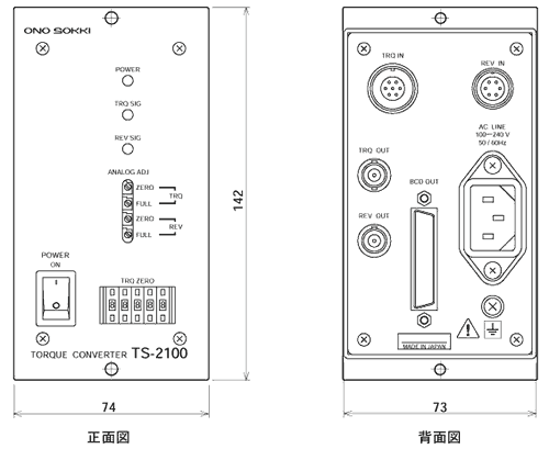
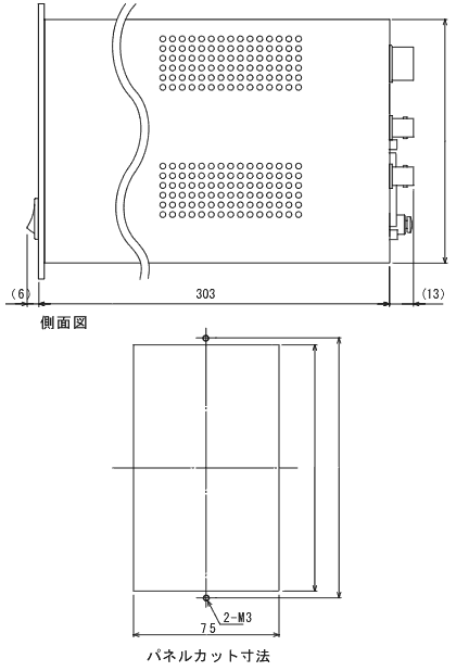
3.outline drawing
Last updated: March 15, 2002