

Torque Meter Frequently Asked Questions
Question number FAQ-1281
Regarding external switching for the motor of the SS type torque detector.
The wiring method for modifying the CW/CCW switching of the motor with SS type torque detector to an external switching method (optional) is shown in the figure below. The power connector changes from 2 pins to 4 pins.
Additionally, the cable is included with a length of 5m (one side: RM15QPS-4SA - one side: open).
- External switching of SS-002 to SS-200, SS-2050 to SS-2200.
A product with a label "OM" attached to the top surface of the detector.
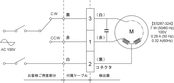
Pin No. 1 2 3 4 detector red black white vacancy Cable red white black green Products without the "OM" seal on the top surface of the detector.
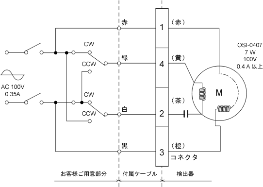
Pin No. 1 2 3 4 detector red tea orange yellow Cable red white black green - External switching for SS-500 to SS-202
A product with a label "OM" attached to the top surface of the detector.
Pin No. 1 2 3 4 detector red black white vacancy Cable red white black green 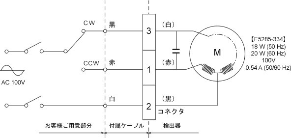
Products without the "OM" seal on the top surface of the detector.
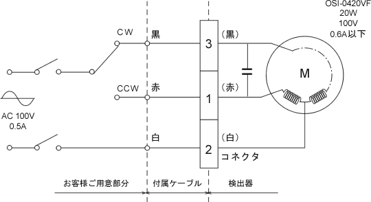
Pin No. 1 2 3 4 detector red white black vacancy Cable red white black green
Attention
Please use a relay contact capacity of around 3 A.
The aforementioned CW and CCW indicate the rotation direction of the detector's axis as viewed from the drive side. The rotation direction of the detector must be opposite to that of the motor attached to it. Therefore, when the switch is flipped to either the CW or CCW side, the axis of the motor attached to the detector actually rotates in the opposite direction.
Last updated date: 2008-06-23