

Torque Meter Frequently Asked Questions
Question number FAQ-1278
Regarding external switching for the motor of the MD type torque detector.
The wiring method for modifying the motor with an MD type torque detector to switch between CW/CCW using an external switching method (optional) is shown in the figure below. The power connector changes from 2 pins to 4 pins. A 5 m cable (one side: RM15QPS-4SA - one side: open) is included.
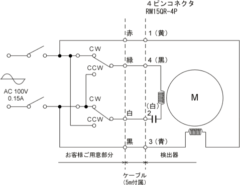
| Pin No. | 1 | 2 | 3 | 4 |
|---|---|---|---|---|
| detector | yellow | white | blue | black |
| Cable | red | white | black | green |
Attention
- Please use a relay contact capacity of around 3 A.
- The aforementioned CW and CCW indicate the rotation direction of the detector's axis as viewed from the drive side. The rotation direction of the detector must be opposite to that of the motor attached to it. Therefore, when the switch is flipped to either the CW or CCW side, the axis of the motor attached to the detector actually rotates in the opposite direction.
Last updated date: 2008-06-23