

Torque Meter Frequently Asked Questions
Question number FAQ-1265
N - 0 Characteristic Correction Function
Even when the shaft is rotating in a no-load state, numbers may appear on the torque display due to the frequency characteristics of the detector and display, as well as the friction torque of the detector. The N-0 correction is used to compensate for this deviation and enable accurate measurements.
During shipping, adjustments are made using electrical components such as resistors for matching adjustments. We verify the FACTOR (phase difference-torque proportional coefficient), N-0 characteristics, and overall accuracy, and attach a test report with the recorded values. The accuracy when the N-0 characteristic correction is OFF is ±0.5% of the rated torque of the torque detector (excluding MD series torque detectors), and when the N-0 characteristic correction is ON, the accuracy is ±0.2%.
The N-0 characteristics, in addition to those of the torque detector alone, also change with the rotational speed when there are mechanical loads such as reducers in the measurement mechanism. By measuring the N-0 characteristics that include these factors and making corrections, more accurate measurements can be achieved. Additionally, the N-0 characteristics vary depending on the type and length of the signal cable, so it is necessary to use the specified dedicated cable.
The method for measuring N-0 characteristics involves removing the coupling of the point you want to measure in a no-load state. For a standalone torque detector, remove the coupling on the load side of the detector. Next, rotate the detector from the drive side and record the torque display values against the rotation speed. Measurements should be taken in both clockwise (CW) and counterclockwise (CCW) directions. By setting this value in the N-0 characteristic correction function, the display will be corrected to show zero during no-load conditions, regardless of rotation. Please note that measurement of rotation speed will be necessary with the TS series display unit. For operation, please refer to the TS series manual on the "N-0 characteristic correction function."
(Example of N-0 correction settings)
Measure the N-0 characteristics in the CW direction. Prepare a table as shown below, and rotate the detection axis with a motor or similar in an unloaded state to record the torque display values for each rotational speed.
≪Note≫
In the count field, enter the number that ignores the decimal point of the displayed value, just like the zero value. The rotation speed is also a number that ignores the decimal point of the displayed value.
| Rotational speed (r/min) | 0 | 500 | 1000 | 2000 | 3000 | 4000 | 5000 | 6000 |
|---|---|---|---|---|---|---|---|---|
| count | -10 | 0 | 5 | 0 | -5 | -5 | -5 |
(Note) The count refers to, for example, a torque display value of 34.56 Nm, which results in a count of 3456.
Next, plot the graph with the horizontal axis as 'rotation speed' and the vertical axis as 'count value', and determine the 'correction' point.
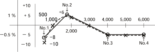
| point | No. 1 | No. 2 | No. 3 | No. 4 |
|---|---|---|---|---|
| Rotational speed (r/min) | 500 | 1800 | 4000 | 6000 |
| correction value | -8 | +6 | -5 | -5 |
It is considered to have a frequency characteristic like −−−− (dashed line). If you perform a linear approximation at 4 correction points, you can select from No.1 to No.4. In the case of the above figure, if you take data more finely around 2000 r/min, where the change is large, you can make finer corrections.
The positive points can be up to 5 points on the TS-2700 calculation display and up to 10 points on the TS-3200 calculation display. Please note that there are types of old TS series calculation displays that do not have the N−0 correction function, so please check the instruction manual.
Last updated: 2011-08-02