

sound level meter Frequently Asked Questions
Question number FAQ-1169
Installation of tripod and microphone extension cable.
Installation of the tripod and microphone extension cable.
List of microphone extension cable types
| type | Name | Compatible microphone extension cable model | |
|---|---|---|---|
| LA-1240 LA-1250 |
ordinary sound level meter | AG-3301型 5m AG-3302型 10m AG-3303型 20m AG-3304型 30m |
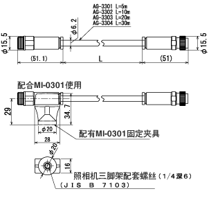 |
| ordinary sound level meter | AG-3305 model with 100m cable reel | 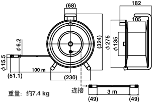 ※ MI-0301 holder included |
|
| LA-1350 LA-4350 |
ordinary sound level meter | AG-2010 model 10m AG-2030 model 30m (coaxial cable) |
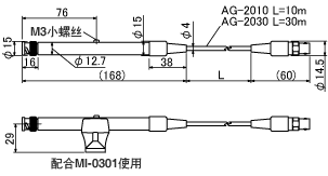
|
| AG-2050 model 50m reel included (coaxial cable) |
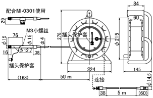 |
||
| precision sound level meter | AG-2100 model 100m reel included (coaxial cable) |
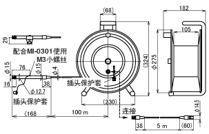 * For each microphone connection outline drawing, please refer to the link below. |
|
The MI microphone holder is included with the microphone extension cable.
Procedure for removing the preamp and installing the extension cable.
- Turn off the power of the sound level meter.
- Loosen the preamp fixed screw (LA-1240/1250) by turning it counterclockwise. Slowly remove it along the connector side of the main body.
- While holding the BNC connector screw (on the LA-1350/4350 main unit connector), turn the BNC connector counterclockwise to align it with the release position, and then slowly pull the preamplifier upwards to remove it.
- Attach the preamplifier to the connector of the microphone extension cable, aligning it and securing it by turning it clockwise.
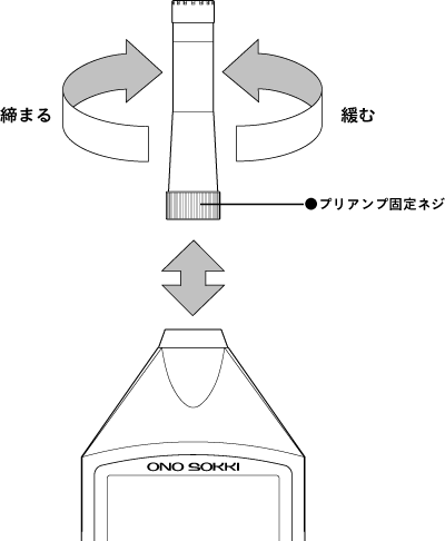
Attachment to a tripod
When directly attaching the sound level meter body to the tripod, it is attached using the tripod mounting screw located on the back of the body.
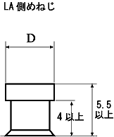
The screw on the bottom of the sound level meter is a screw for camera tripods. It is a "1/4" screw in accordance with JIS B7103. (The sound level meter side is a female screw.)
 |
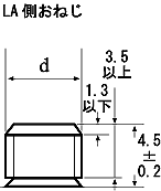 |
Unit: mm
| call | Number of threads (per 25.4mm) n |
pitch | male thread | male screw | |||||
|---|---|---|---|---|---|---|---|---|---|
| outer diameter d | effective diameter | Path of the Valley | Diameter D of the valley | effective diameter | inner diameter | ||||
| 1/4 | 20 | 1.270 | reference dimension | 6.350 | 5.525 | 4.975 | 6.350 | 5.525 | 4.975 |
| Maximum allowable dimensions | 6.322 | 5.497 | 4.763 | not regulated | 5.820 | 5.267 | |||
| minimum allowable dimension | 6.012 | 5.355 | not regulated | 6.460 | 5.635 | 4.975 | |||
| tolerance | 0.310 | 0.142 | --- | --- | 0.185 | 0.292 | |||
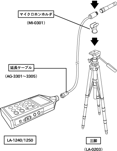
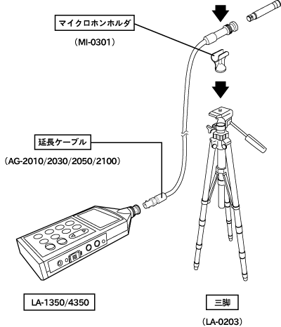
When installing the microphone and preamp away from the main unit,
- Attach the microphone holder to the tripod.
- Attach the preamp connector of the extension cable to the microphone holder on the tripod.
In the case of LA-1240/1250
In the case of LA-1350/4350
Last updated date: 2004-11-15