

DR-7100 Frequently Asked Questions
Question number FAQ-1125
How to display sound data collected from a sound level meter and microphone as sound pressure level using the OS-2000 series (Part 2)
1. Import the calibration sound file containing the recorded calibration sound and the recorded data file you wish to calibrate into the OS-2000 series. Note that the equipment and amplification settings used when recording the calibration sound data must be identical to the equipment and amplification settings used for the data recording.
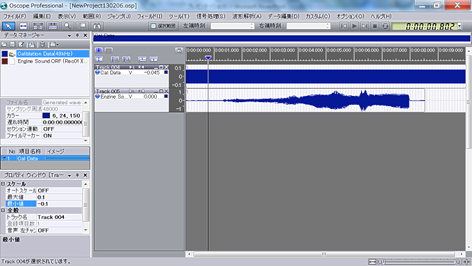
The figure above shows the sound data recorded using the DR-7100 imported into the OS-2000 series. The upper part is the data file containing the recorded calibration sound (94 dB), and the lower part is the data file containing the recorded engine intake sound. The unit of magnitude is 'V'.
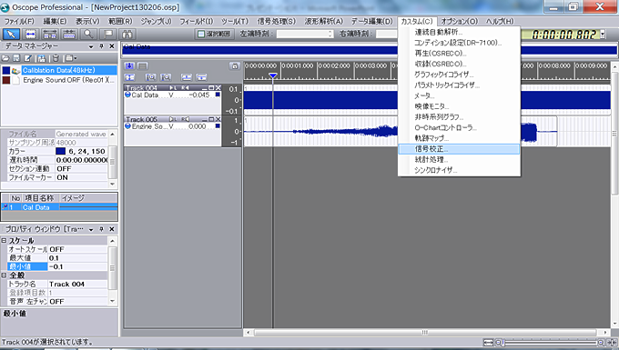
2. Perform calibration to sound pressure using the upper calibration sound data file. Select "Signal Calibration" within "Custom" on the OS-2000 series toolbar. The signal calibration window will open.
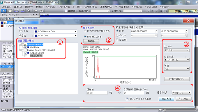
1. Select the file containing the calibration sound as the "calibration signal (reference signal)". Next, choose the data file you want to calibrate from the options displayed under "Select Calibration Items" and check the checkbox.
2. Select 'calibrate using FFT' in 'how to calibrate'. The default for the 'calibration signal (reference signal) interval' is set to 'entire interval', but since this may be too long or the signal may not be stable at the start of the measurement, choose an interval where a stable signal is output. (Please select an interval of several seconds, around 10 seconds.)
Set the 'scale' to 'decibels', the 'calibration target' to 'overall', and the 'unit' to 'rms'.
Set the "target value (level after calibration)" to the sound pressure level of the calibration sound (here set to 94 dB) and click on "Execute Calibration."
By checking 'Output to a new channel' and executing the calibration, a new data file with the rewritten calibration scale will be created in addition to the original data file.
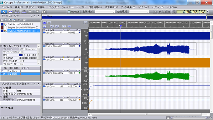
The top file is the original calibration sound data, the third from the top is the calibration sound data after performing "signal calibration." The second from the top is the engine intake sound data, and the fourth from the top is the data after performing "signal calibration." In the files after calibration, it can be seen that the unit of the signal has changed from "V" to "Pa." The fifth from the top is the result of performing "effective value calculation" on the original calibration sound data. The sixth is the result of performing "effective value calculation" on the calibration sound data after "signal calibration." What was -28 dB has become 93.999 dB.
Last updated: 2017-07-12