

Frequently Asked Questions about the Tachometer
Question number FAQ-0934
The display of the TM-3100 is unstable (it counts incorrectly).
 TM-3100 Series Digital Tachometer Installation Manual Short Version (PDF 1.2 MB)
The TM-3100 is highly sensitive and may be affected by high-frequency noise on the signal line, which can cause variations in rotation speed. Be sure to implement the noise countermeasures described in the instruction manual.
Also, when making it EMC compliant, please download the "TM3100 Installation Manual" and be sure to follow the instructions for storing in a metal panel, using line filters, surge killers for power wiring, and handling signal shielded wires.
Noise countermeasure wiring
- Please ensure to ground the GND of the main power terminal.
Grounding Type 3 grounding or higher (below 100Ω), soft copper wire of 2 mm 2 or more (AWG14), maximum grounding extension of 20 m -
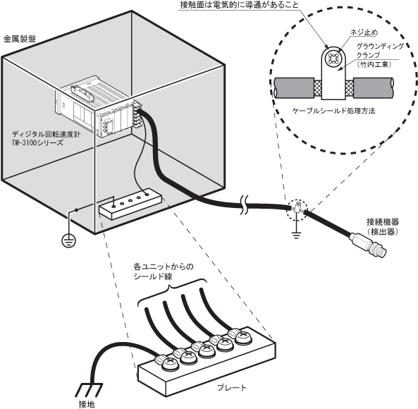
Please connect the shields of all input and output signal cables to a stable ground at both ends.
Refer to the following diagram and wire the signal cables as short as possible.
Please keep the negative side wiring of the surge killer within 50cm.
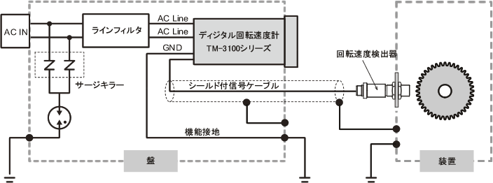
part name Manufacturing Company Name Model name number of items line filter TDK Corporation ZHC2203-11 1 Surge Killer Phoenix Contact Inc. F-MS 12ST 1 Surge Killer Phoenix Contact Inc. VAL-MS 230ST 2 Base for Surge Killer Phoenix Contact Inc. VAL-MS-BE 1 Refer to the following diagram and ground the shield using grounding. It is recommended to use the EMT series grounding clamp from Takeuchi Industries. Additionally, if the optional EXTERNAL unit TM-0350 (RS-232C + GATE) is incorporated in slot B, the RS232C cable should be grounded within 10 cm of the digital tachometer TM3100 series, and there is no need to ground on the personal computer side.
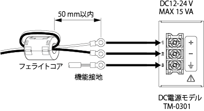
If the optional DC power unit TM-0301 is installed in the POWER slot of the TM-3100, please connect the cable to the DC power module located in the POWER slot according to the following diagram. Be sure to use the ferrite core made by Seiwa Electric (E04SR301334), and make sure to loop the cable through the ferrite core twice.
Last updated: June 14, 2012