

Frequently Asked Questions about the Tachometer
Question number FAQ-0933
Is the TM-3100 series compatible with the older TM-800/8000 series and TM-2100 series?
The TM-3100 series is compatible with the older models TM-800/TM-8000 series and TM-2100 series. As before, there are four basic sets available: TM-3110 (display only), TM-3120 (BCD open collector output), TM-3130 (analog output), and TM-3140 (comparator output).
However, to ensure compatibility with the TM-2120 (model with BCD output), it is necessary to change to the TM-0321 BCD output card (voltage output), resulting in a combination of TM-3110 and TM-0321.
The output current of the TM-800/8000 series and TM-2100's BCD output was 4 mA, but the voltage output of the TM-0321 is designed with a circuit that pulls up to +5 V internally with a 10 kΩ resistor in an open collector output.
Please be careful with the connection in the case of receiving circuits with impedance and current flowing into the receiving circuit.
Supplementary explanation
In the TM-3100 series, in addition to the conventional features, we have added the new function "SS measurement" and the optional "TS-0350 (RS232C/GATE)".
The basic concepts of the TM-3100 series are as follows.
Measure the 'frequency' of the input signal and perform calculations to display the values in the units of each measurement item.
The "measurement methods" include "NORMAL (normal continuous measurement)" and "SS (start-stop average measurement)."
By simply setting the units for the measurement items, it automatically converts and displays the units.
This section explains the measurement methods and an overview of the measurement items. Please refer to the user manual for information on the computational functions of the TM-0350 (RS232C/GATE) and measurements using gates.
Measurement Method (MEAS MODE)
1-1 NORMAL
For example, measurements are repeated and updated according to the set data update time of "1s". NORMAL performs general rotational speed and line speed measurements, and is compatible with the same measurement methods as the old models TM-800, 8000 series, and TM-2100 series.
1-2 SS (START・STOP)
This is a function to measure the AVERAGE, MAX, and MIN of a measurement interval. There are two types of measurements: MANUAL and AUTO, depending on the start and stop conditions of the measurement interval. In the case of "MANUAL," the measurement interval is set using the START and STOP buttons (or the external input of TM-0350). In the case of "AUTO," it is set by the start conditions and measurement time.
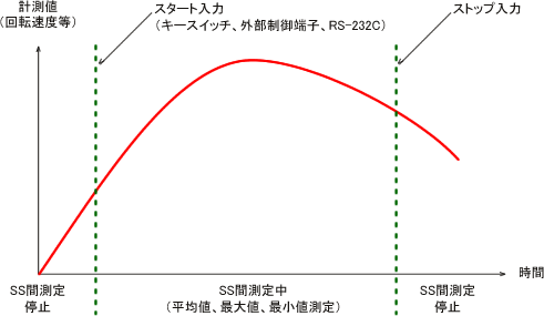
■SS−MANUAL (Manual)
Select "MANUAL" in [SS MEASUREMODE]. In MANUAL measurement, the average value and other measurements are taken from the point the START button is pressed to the point the STOP button is pressed.
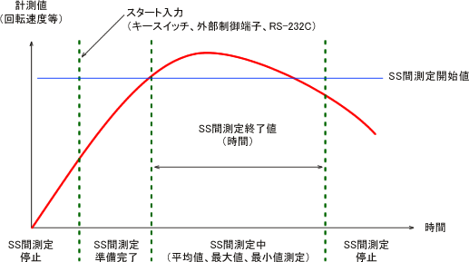
■SS−AUTO (Auto)
Select "AUTO" in [SS MEASUREMODE]. In AUTO measurement, when you press the START button, it enters the ready state. Measurement starts when the set start conditions are met, and it measures averages, etc., over the interval defined by the stop conditions for the set measurement time.
For example, with settings of "START: 2000 r/min, STOP: 10 s", if you press the START button at 1000 r/min and gradually increase the rotation to reach 2000 r/min, measurement will start and it will measure AVERAGE, MAX, and MIN over the interval until 10 s has elapsed. Alternatively, for example, if you press the START button at 2500 r/min and decrease the rotation to reach 2000 r/min, measurement will start. Please pay attention to the rotation speed when pressing the START button.
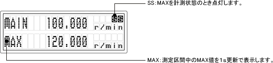
Main screen and sub screen
In setting mode, by selecting [DISPLAY] → [2 LINES], the main screen displays the NORMAL measurement values, while the sub-screen shows the selected value among SS measurement values: AVERAGE, MAX, or MIN. The figure below shows an example of the main screen and the main sub-display that has been set.
● TM-3140 (with comparator) main screen (in case of 1 LINE display) |

● TM-3110 (display only) main + sub screen (in the case of 2-line display) |
Measurement items
The TM-3100 series measures the period (frequency) of the input signal. Using the measured frequency, calculations are performed using the values set in the measurement items as coefficients, and displayed in the specified units.
The measurement items and formulas are shown in the table below.
| Measurement items | display unit | expression |
|---|---|---|
| ROTATION Rotation speed | r/s、r/min、r/h | Rotation speed = Measured frequency ÷ PULSE × FACTOR × K |
| L.SPEED Speed | mm/s、m/s、mm/min、m/min | Circumferential speed = Measured frequency ÷ PULSE × DIAMETER × π × FACTOR × K |
| VELOCITY movement speed | mm/s、m/s、mm/min m/min、km/minmm/h、m/h、km/h | Moving speed = Measured frequency ÷ PULSE DISTANCE × FACTOR × K |
| PERIOD cycle | s、min | Period = 1 ÷ Measured Frequency × K |
| TIMES number of times | 1/s、1/min、1/h | Count = Measurement Frequency × FACTOR × K |
| FREQ Frequency | Hz、kHz | Frequency = Measurement Frequency × FACTOR × K |
| FLOW Flow | ml/s、ml/min、ml/h l/s、l/min、l/h | Flow = Measurement Frequency × FACTOR × K |
| P.TIME Elapsed time | s、min | Passage time = PROCESS LENGTH ÷ Peripheral speed × FACTOR × K (Peripheral speed = Measurement frequency ÷ PULSE × DIAMETER × π) |
| OTHER Engineering Units | EU/s、EU/min、EU/h | Engineering unit = Measurement frequency × FACTOR × K |
Example of using FACTOR: For instance, if there is a speed reducer and the installation position of the detector is at the input shaft while the rotational speed to be displayed is at the output shaft, the reduction ratio should be set in the FACTOR. Normally, FACTOR is used with a setting of '1'.
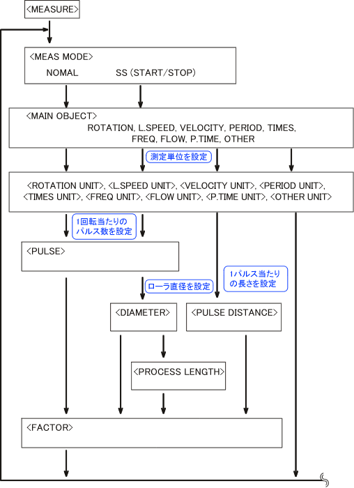
2-1 Setting Mode (MEASURE)
In the setting mode "MEASURE", you will configure the "measurement method" along with the related "measurement items" and "measurement units". Whether you choose the measurement method NORMAL (normal continuous measurement) or SS (start-stop average measurement), the settings for measurement items and measurement units will be the same. Generally, NORMAL (continuous measurement) is used. The flow of the setting operations in the setting mode "MEASURE" is shown in the next figure.
2-2 Setting Mode (FUNCTION)
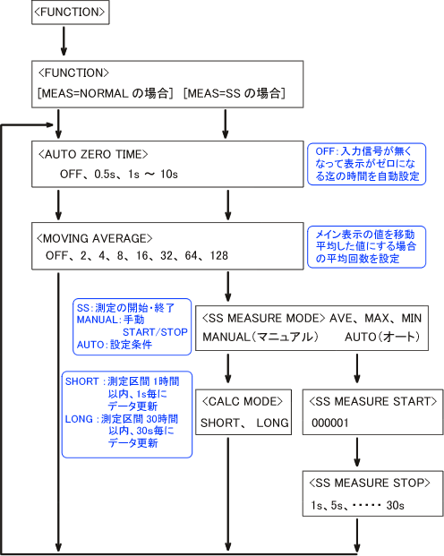
In the setting mode "FUNCTION", you can set the display content related to the measurement methods "NORMAL" and "SS", as well as the start and stop conditions for SS measurement. In the case of "NORMAL", continuous measurement is performed with automatic updates, so there are no start and stop condition settings. The flow of the setting operations in the setting mode "FUNCTION" is shown in the following diagram.
Last updated: 2009-08-24