

Frequently Asked Questions about the Tachometer
Question number FAQ-0925
Example of setting for TM-3100 series tachometer - 4 "Setting procedure for rotation measurement using MP-9100 rotation detector"
<Caution regarding operational instructions> The menu items in setting mode are "INPUT → MEASURE → FUNCTION → DISPLAY → OUTPUT → OTHER." The settings for each menu item are shown in a flowchart, with selections indicated by a □ red frame and setting values noted as subscripts. For items without a □ red frame, press the [SET/NEXT] button to pass. Please perform button operations following the arrows in the flow. The explanation of button operations is omitted, as you can refer to the section <Basic Button Operations> below. |
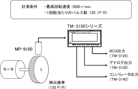
Measurement Conditions
| detector | MP-9100 |
|---|---|
| detection gear | 120 P/R |
| Decimal point and display unit | ○○○○ r/min |
| BCD output | Continuous update output |
| Analog Output | 0 ~ 10V / 0 ~ arbitrary r/min |
| comparator | Arbitrary settings |
<Example of the rear panel for the TM-3100 series>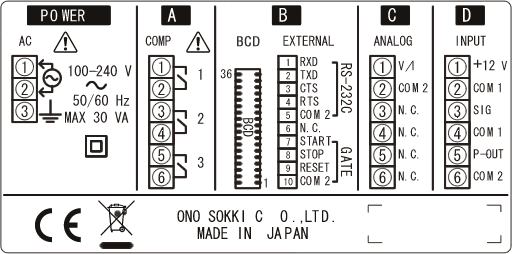
Wiring Method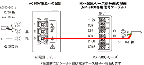
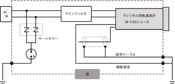
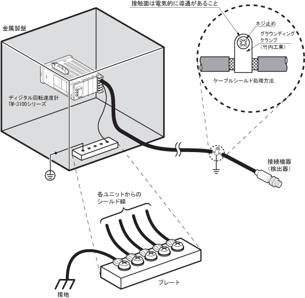
Please be careful To ensure EMC compliance, please download the 'TM-3100 Installation Manual' and be sure to follow the instructions for housing in a metal panel, using line filters and surge protectors for power wiring, and handling signal shielded cables. ■EMC Suitable Configuration and Wiring Diagram |
Basic Button Operations
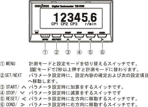
Press the 'MENU' button to enter the settings mode.
Pressing the 'MENU' button briefly will return to the previous item.
By long-pressing the 'MENU' button, you can switch to measurement mode (display of measurement values) from any position.
Settings
INPUT (Input Settings)
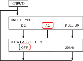
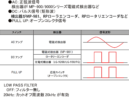
In [INPUT], settings related to the acquisition of input signals are configured. Here, we will assume the following settings.INPUT TYPE AC LOW PASS FILTER OFF After finishing the settings, press the [SET/NEXT] button.
MEASURE (Setting of Measurement Function)
In [MEASURE], you will set the measurement method, measurement items, and their conditions. Here, we will assume that the number of teeth on the detection gear is set to 120, as follows.MEASURE MODE NORMAL MAIN OBJECT ROTATION ROTATION UNIT r/min PULSE 120 (number of teeth of the detection gear) FACTOR 1.00000 × 10E+0 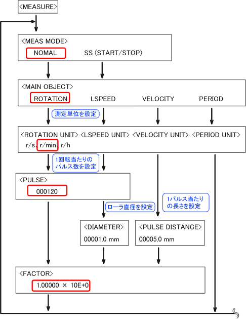
FUNCTION (Display method and measurement start/stop)
In [FUNCTION], you will configure the display method and measurement start/stop settings. Here, we will assume the following settings.AUTO ZERO TIME OFF MOVING AVERAGE OFF 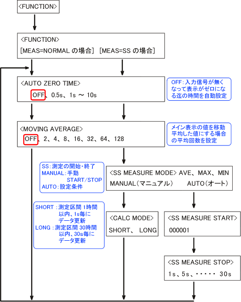
-
DISPLAY (Display Screen Settings)
In [DISPLAY], settings related to the number of display digits and display updates are configured. Here, we will set it as follows.DISPLAY 1 LINE D.P. POSITION OFF DIGIT FIXED TO 0 OFF DISPLAY UPDATE 1.0s BRIGHTNESS MID 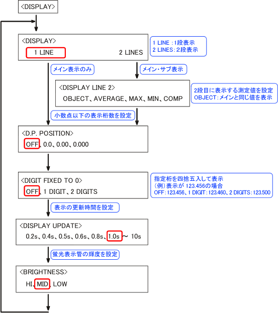
-
OUTPUT (Settings for BCD, COMP, and ANALOG outputs)
In [OUTPUT], settings related to BCD output, comparator output, and analog output are configured. Here, we will assume the following settings.BCD OUTPUT MAIN (display value) BCD MODE CONTINUE (Continuous Update) COMP MODE UPPER LOWER
(Optional settings for each COMP1, 2, 3
UPPER: Measured value ≧ Set value
LOWER: Measured value < Set value)COMP UPPER (LOWER) Set arbitrary judgment values for COMP1, COMP2, and COMP3. ANALOG OUTPUT MODE VOLTAGE ANALOG VOLTAGE RANGE 0 to 10 V ANALOG ZERO 000000 ANALOG FULL Set the desired display value to 10 V. ANALOG UPDATE 10 ms
(If the signal is slow due to periodic operation, the voltage change will be delayed)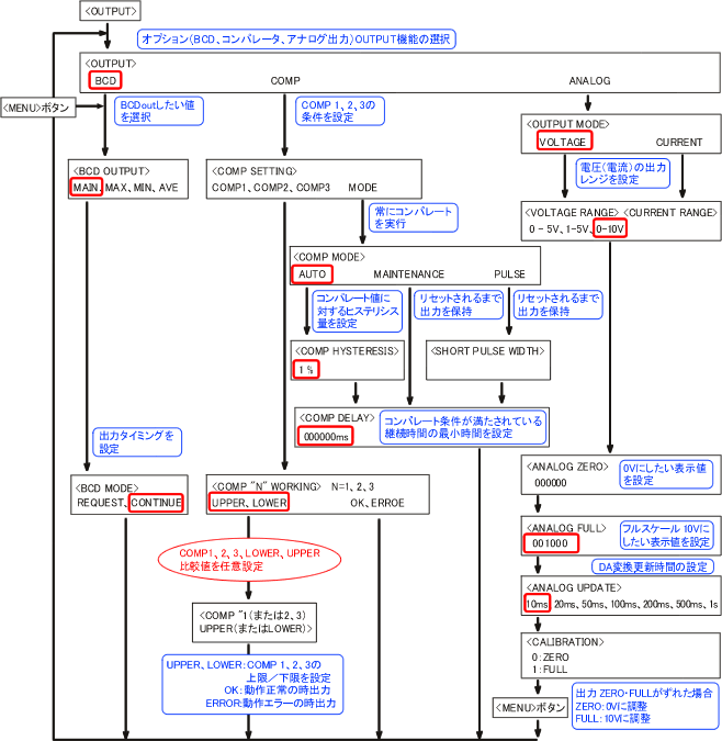
-
OTHER (Panel Condition Save)
In [OTHER], settings for saving/loading conditions, RS-232C, and options list are configured. The setting values are saved in backup memory, but for safety, they will be saved in COND1.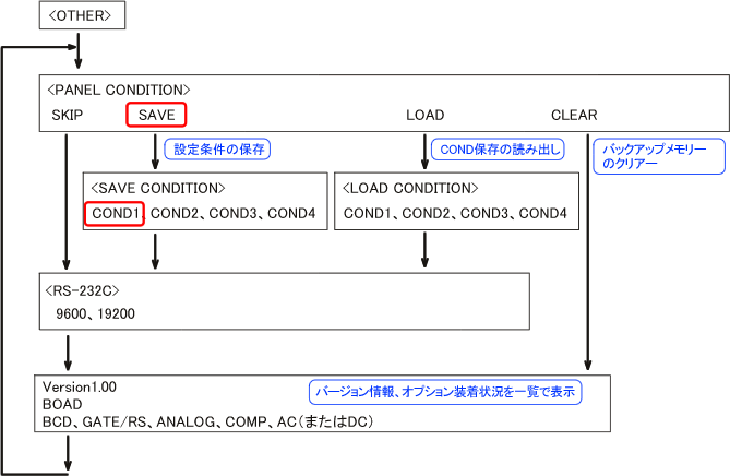
About saving settings. - Backup Memory
The menu settings are saved in the backup memory. When the power is ON, the settings from the backup memory are automatically read. - CLEAR
Restores the contents of the backup memory to the default settings (factory settings). - CONDITION
The settings of the backup memory can be stored (SAVE) to COND1.
You can read from the backup memory with the LOAD operation.
- Backup Memory
Return to measurement
Press and hold the [MENU] button. This will return to the measurement screen and start the measurement.
Last updated date: 2013-10-28