

Frequently Asked Questions about FV Converters
Question number FAQ-0916
I am using LG-916 and TM-2130 together, but the output voltage remains at zero. I am also using LG-930 and FV-1100 together, but the output voltage fluctuates in a wave-like manner.
When a reflective sticker is applied to the axis, the signal detected by photoelectric detectors such as the LG-916 and LG-930 results in a low number of pulses per second. Depending on the rotation speed to be measured, this can become extremely low relative to the frequency range of the FV conversion circuit, resulting in an output voltage as described in the question.
Explanation
The TM-2130 and FV-1100 utilize an FV conversion circuit (frequency/voltage conversion circuit) to convert the frequency of the input signal into a voltage that is proportional to it.
The following figure shows the block diagram of the FV conversion circuit.
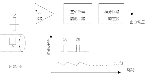
The integrator circuit charges when the input pulse is at a high level and discharges when it is at a low level. As the frequency of the input pulse increases, the number of charging instances increases, leading to a longer overall charging time, which causes the output voltage to rise. Conversely, when the frequency decreases, the discharging time becomes longer than the charging time, resulting in a decrease in output voltage.
The speed of charging and discharging is faster with a smaller time constant, and the difference in voltage during a single pulse (referred to as ripple) becomes larger. Furthermore, this ripple is minimal at high input frequencies but becomes more significant at lower frequencies.
Photoelectric detectors such as the LG-916 and LG-930 only output signals based on the number of reflective stickers applied per rotation, which tends to result in low input frequencies, leading to the issues described. It is necessary to calculate the input frequency from the operational rotation range and confirm whether it can be used at more than 10% of the frequency range for FV conversion.
The catalog for the TM-2130 lists the amount of output voltage ripple when the frequency is at 1% of the frequency range. The table below is an excerpt of one such example.

Accuracy as stated in the catalog.
Voltage output 0.1 % FS
Current output 0.7 % FSThe precision is worst at 20 kHz, so the resolution and the accuracy of the analog circuit at this time are documented.
It can be modified to an input frequency of up to 50 kHz. In this case, the resolution will also be considered similarly.
Last updated: July 13, 2018