

Magneto-Electric Rotation Detector
Question number FAQ-0856
Operating Principle of MP-9810 / MP-9830 Magneto-Electric Rotation Detector
The MP-9810 / MP-9830 Magneto-Electric Rotation Detector incorporates magnetic resistance elements, permanent magnets, DC amplifiers, and voltage regulators to measure the rotation speed of gears from ultra-low to high speeds.
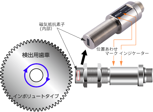
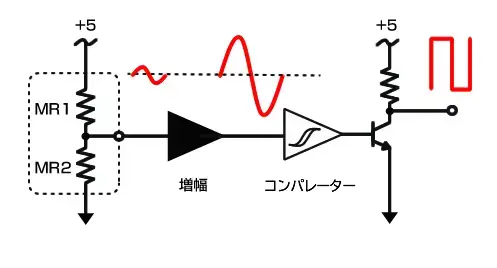
The MP-9810 / MP-9830 has a detection part equipped with magnetoresistive elements at the sensor tip. This detection part consists of two magnetoresistive elements, MR1 and MR2, and a magnet. By shaping the signal waveform detected by this detection part, the MP-9810 / MP-9830 obtains a rectangular wave output.
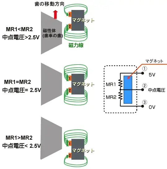
The detection unit consists of two magnetoresistive elements, MR1 and MR2, and a magnet, as shown in the figure below. The magnetoresistive elements exhibit a resistance value that is proportional to the magnitude of the applied magnetic field. When a magnetic object (gear) is present in front of the sensor, the strength of the magnetic field changes. As a result, if the position of the magnetic object is unbalanced with respect to each magnetoresistive element, the resistance values will also be unbalanced. By applying a constant voltage between terminals ① and ③, and observing the output voltage at terminal ②, the output signal from terminal ② changes in a manner that traces the shape of the gear.
When the gears rotate, the changes mentioned above will continue to occur. (See the figure below.)
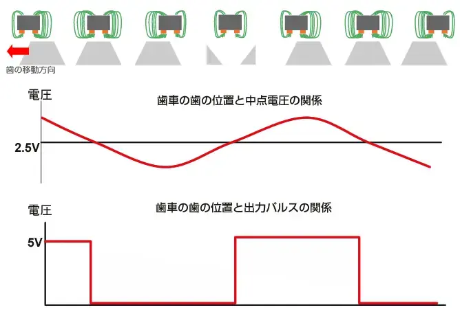
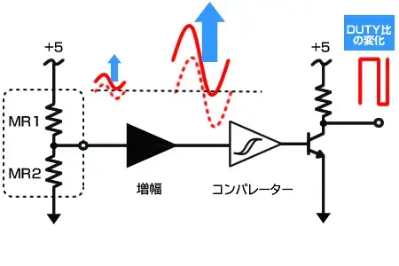
The signal obtained from the magnetoresistive element is shaped into a final signal. Since the signal amplitude from the magnetoresistive element is small, around tens of mV, changes in midpoint voltage due to temperature variations or increases in rotation speed can lead to changes in the duty cycle or the loss of rectangular wave output.
Last updated: 2025-03-27