

Frequently Asked Questions about FV Converters
Question number FAQ-0839
Precautions for inputting the output voltage of FV-1400 into a computer AD conversion board.
When the input and output signals of the FV-1400 are connected to an AD conversion board built into a computer, noise from the sample clock of the AD conversion board may be present. The figure below shows an example of noise waveforms present in both the input signal and output voltage.
Example 1
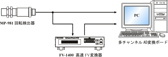
The noise waveform superimposed on the analog output signal of the FV-1400.
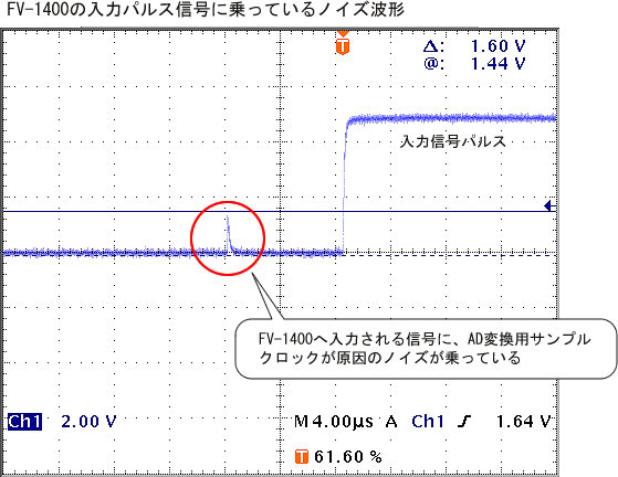
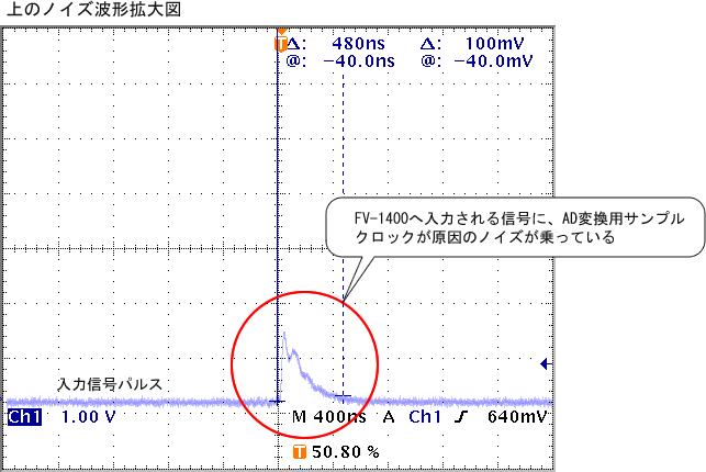
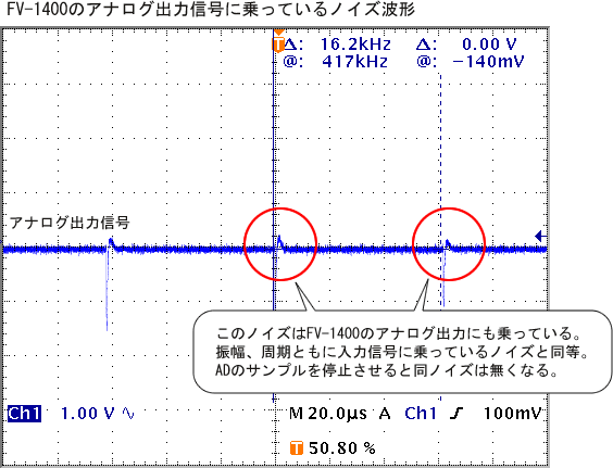
Example 2
In the above figure, even when only the output signal of the FV-1400 is connected to the AD conversion board, noise caused by the same sampling clock can be superimposed on the output voltage and may even loop back into the input signal. If the FV-1400's input is used in 'AC coupling', there can be cases of malfunction due to noise superimposed on the input signal, leading to incorrect measurements.
Measures
In such cases, please try the following measures. In the above example, it was possible to address the issue by combining (1) and (2).
(1) Sensor signals should preferably pass through an amplifier and use a "rectangular wave signal" output like that of the MP-981 rotary detector. The input coupling for the FV-1400 should be set to "DC coupling."
Adjust the trigger level of the FV-1400 to a level that does not pick up noise.
(3) Confirm the noise countermeasure methods with the AD conversion board manufacturer.
(4) To prevent the sampling clock of the AD conversion board from interfering with the input signal, either adjust the output voltage of the FV-1400 or add a filter circuit (such as an isolation amplifier) to the input signal. The filter circuit should be provided by the customer.
Last updated date: 2002-02-15