

DS-2000 Frequently Asked Questions
Question number FAQ-0675
What should I do if I mistakenly set the rotation pulse count during measurement with the DS-0222 tracking analysis software?
When conducting tracking analysis, if the number of rotation pulses is incorrectly set, the displayed value of the rotation speed will differ from the actual rotation speed. As a result, the frequencies that were intended to be analyzed will not match the set frequencies. Since the data saved in TRC files (tracking data) and ORF files (DS-0250 data recording) cannot be changed, when performing tracking analysis again using this data, the settings must be adjusted to correspond to the desired frequencies that are compatible with the saved data.
For example, after setting the parameter to 20 P/R at the point of 30 P/R and reading the measured TRC or ORF file, I will explain how to analyze it with the desired order of analysis set to 1st order and the measurement range from 1200 r/min to 3600 r/min.
■ Operating Procedures
The relationship between measured rotation speed and actual rotation speed.
Originally, the value that should be displayed at 1200 r/min is measured (and displayed) as 1800 r/min according to the following formula.
Ho = 1200 r/min ÷ 60 s ×30 P/R = 600(Hz)
R = 600 Hz ÷ 20 P/R × 60s=1800(r/min) In summary; Measured rotational speed = Actual rotational speed × 30 ÷ 20Actual rotational speed = Measured rotational speed × 20 ÷ 30 |
Therefore, since the original measurement range of 1200 r/min to 3600 r/min is displayed as 1800 r/min to 5400 r/min, we will set it to this value.
conversion of attention counts
The actual rotational speed is 20 to 30 times the measured rotational speed, so taking this into account, the formula for determining the setting number is as follows.
| Setting frequency = Attention frequency × 20 ÷ 30 (Attention frequency: The frequency you wanted to analyze) |
In the case of 1 occurrence of attention;
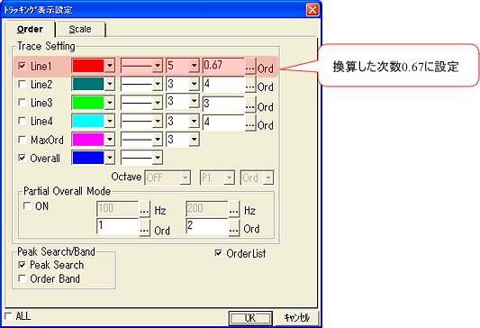
| Setting frequency = 1 × 20 ÷ 30 = 0.67 |
Therefore, the 'tracking display settings' will be set to 0.67 ord.
Please note that the rotation speed and frequency displayed on the re-analyzed tracking screen will remain as recorded data.
To make the original measurement from incorrect setting data.
This shows how to set the upper and lower limit rotation speed in the settings screen of the dialog opened from the menu by selecting [Input] ⇒ [Tracking Measurement].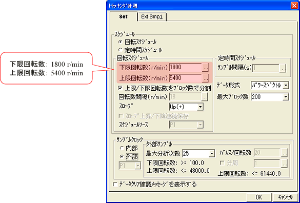
This shows the setting screen of the dialog opened from the menu by selecting [Data Display] ⇒ [Tracking Display Settings], configured to a conversion factor of 0.67 (Peak Search on).
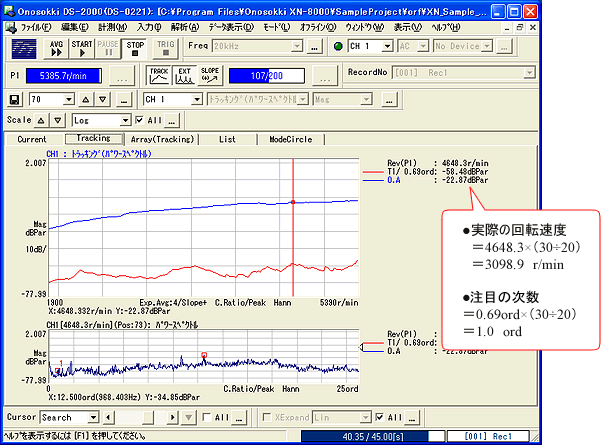
Example of measurement data
The degrees of the X and Y axes will be displayed as per the previous data, so they need to be converted for interpretation. Note that the degree 0.67 is not multiplied by the resolution, which is why it is displayed as the more recent degree of 0.69.
Supplementary explanation
Let's consider order 1 in terms of frequency.
Incorrect settings (20P/R)
If the rotational speed display shows an incorrect value of 1200 r/min, the primary setting will also measure incorrect points. The primary frequency at 1200 r/min is;
| 1200 ÷ 60 × frequency 1 = 20 Hz |
Correct setting (30P/R)
The correct rotational speed when the display shows 1200 r/min is 800 r/min, so the primary frequency at 800 r/min is
| 0 ÷ 60 × frequency 1 = approximately 13.3 Hz |
To see the original measured frequency of 1st order, it becomes "13.3 Hz: 20 Hz = x:1st order, thus x = approximately 0.67 order," so it is necessary to look at this order.
Last updated: March 16, 2009