

Digital Gauge Frequently Asked Questions
Question number FAQ-0118
Output specifications of the linear gauge sensor and connector specifications.
I will describe the signal output circuit of the GS・BS series linear gauge sensor.
Signal output
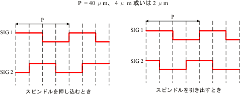
The output is provided as a 2-phase pulse signal from the sensor. The distance per pulse is shown in the table below.
If connecting to devices other than our display, it is necessary to use a multiplication circuit for direct reading, converting to 10μm per pulse and 1μm.
Please be aware of noise and other factors.
| Minimum display unit for GS and BS sensors | the distance between one pulse |
|---|---|
| For 10μm unit sensor | 40 μm |
| for 1μm unit sensor | 4 μm |
| GS-7000 Series | 2 μm |
| GS-3800 Series | 0.4 μm |
■ Output circuit, connector wiring diagram
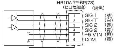
The output circuit varies by model, with four types available.
|
GS-1713/1730/1813/1830/4713/4730/ 4813/4830/6713/6730/6813/6830/5050/5100/5051/5101 |
|---|
|
|
| BS-102/102W/112/112W |
|
|
| GS-7710A/7710NA |
|
|
| GS-3813/3830 |
|
|
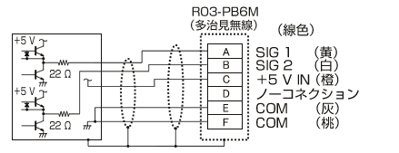
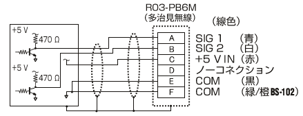
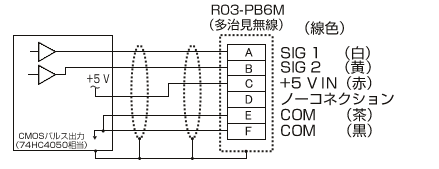
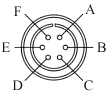 R03-PB6M |
Pin No. | signal name | Line color GS series (excluding 7000/3800 series) |
Line color GS-7000 series |
Line color BS series |
| A | SIG 1 | yellow | white | blue | |
| B | SIG 2 | white | yellow | white | |
| C | +5 V IN | orange | red | red | |
| D | NC | unused | unused | unused | |
| E | COM | ash | tea | black | |
| F | COM | peach | black | Green Orange (BS-102) |
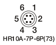 |
Pin No. | signal name | Line color GS-3800 series |
| 1 | SIG 1 | tea | |
| 2 |  |
white | |
| 3 | SIG 2 | red | |
| 4 |  |
blue | |
| 5 | +5 V IN | orange | |
| 6 | COM | yellow |
Last updated: 2013-05-20