

Digital Gauge Frequently Asked Questions
Question number FAQ-0076
Overview of DG-4320/4340
We will perform dimensional measurements in combination with the GS series gauge sensor. It will also operate as a counter in conjunction with an encoder.
Front panel
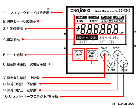
1. Comparator mode status display (only for DG-4340)
GATE: Displayed when the comparator function is disabled due to external input
COMP1/COMP2/COMP3: Displayed when comparator 1/2/3 output is ON
Calculation Mode Status Display
START: Display when MAX/MIN/RANGE operation begins
MAX/MIN/RANGE: Display operation mode
Measurement Value Display
Display each data of instantaneous value/MAX/MIN/RANGE calculations.
Settings Display
Display data in various formats during the setting/confirmation of parameter values.
5. Mode Switch
Switching between measurement mode and setting mode.
Confirmation of setting conditions and moving to the next item.
Key for confirming the content of condition settings or for moving to the next item in the condition settings.
Confirmation of setting conditions and upward movement
COND:Check the setting conditions
∧: Move the condition setting cursor up
Start of calculation and downward movement
START: Keys for starting operations of MAX/MIN/RANGE. (Automatic deletion of past data)
∨: Move down the condition setting cursor
Stopping of calculations and left shift
STOP: Stop the operation
10. Reset/Keep Protect/Move Right
RESET: Resets instant values and various calculated values. It will not reset while calculations are in progress. Please reset after stopping the calculations.
By holding for more than 2 seconds, key protect is activated. If key operations are performed during key protect, a message (KEY PROTECT) will be displayed. Key protect can be released by holding for more than 2 seconds again.
>: Moves the condition setting cursor to the right.
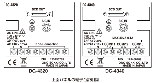
Back panel

11. BCD OUT Connector
Connector for BCD output, control output, or external command signal input.
12. Protection setting terminal
Always ground to prevent electric shock and remove noise.
13. Signal Input Connector
Input signals from gauge sensors and rotary encoders.
14. Power input terminal
Input power of AC 100 to 240 V (50/60 Hz).
Comparator Output Terminals 1/2/3
Output at one make contact when each comparator is ON.
top surface sticker
Last updated date: 2013-03-18