

Digital Gauge Frequently Asked Questions
Question number FAQ-0072
DG-4280 Back panel and terminal block connection
I will explain how to connect to the terminal block. For more details, please refer to the instruction manual.
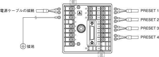
Connection to the cable
The terminal block uses M3.5 screws. It is recommended to use round crimp terminals that match these screws.
Grounding
For safety and noise reduction, please ensure that the grounding terminal (no.3) is grounded. Grounding should be done at one point at the grounding terminal, and do not perform any bridging with latitude lines.
Grounding type: Type 3 or higher (below 100Ω)
Ground wire: Soft copper wire of 2mm2 or more (AWG14)
Ground extension: Up to 20m
Connection of relay output
When connecting inductive loads (such as relays) to the relay output (No. 10 to 15) on the back panel, please use protective circuits to keep back electromotive force low and prevent damage to the relay contacts.
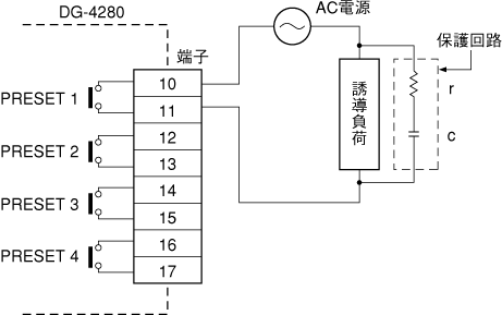
The guideline for c and r is
c: Contact current 1A corresponds to 0.5–1μF
r: Contact voltage 1V corresponds to 0.5–1Ω
However, due to the nature of the load and variations in relay characteristics, the above may not always be the case. Please confirm through experiments that 'c' is responsible for the discharge suppression effect when the contacts are open, and 'r' plays the role of current limitation during the next activation. Use capacitors rated between 100V and 300V for 'c'. In AC circuits, use capacitors suitable for AC (non-polarized). If the load is a relay or solenoid, the recovery time will be delayed.
Connection of external devices
When inputting preset gate signals, hold signals, and reset signals from external devices, connect the signals to the terminal block on the rear panel.
Please refer to DG4280 terminal block input signal timing chart.
(5) Installation of terminal block cover (optional)
A terminal block cover (model DG0420) is available.
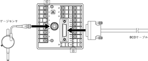
(6) Connection of GS sensor and BCD signal cable
Connect as shown in the figure below. The signal cable for the BCD connector is available as an option in the AA8107 model (3m long, one side open).
For BCD OUT, please refer to DG4280 BCD out specifications.
Last updated: 2000-12-08