

Digital Gauge Frequently Asked Questions
Question number FAQ-0070
DG-4280 Names and Functions of Each Part
Combination dimensions will be performed with the gauge sensor. It is compatible with all GS series, including both new and old models.
Front panel
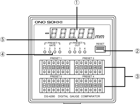
<1> Display Section
The measurement is displayed in 5-digit numbers in mm. When the measurement is negative, the "−" indicator on the left lights up. In case of a measurement error, the displayed value will blink. (Please refer to the troubleshooting section)
<2> RESET switch
When the switch is pressed, the displayed value, BCD output, and error output are reset.
<3> PRESET1~4 Digital Switch
Sets the preset values for judgment.
<4> PRESET GATE1~4
The preset gates (1 to 4) will light up in red while they are being input from the rear panel terminal block. While lit, the judgment output is forcibly stopped and will be turned OFF.
<5> PRESET OUT1~4
It lights up when the set value meets the output conditions of each preset. Preset output conditions (common to PRESET 1~4)
Set polarity = measurement polarity and |set value| ≦ |measurement value| when
Back panel
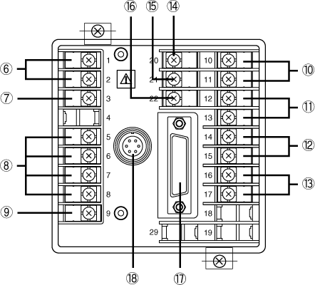
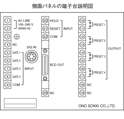
<6> Power Input Terminal (No.1, 2)
Inputs power of AC100V to 240V.
<7> Ground terminal (NO.3)
Always ground it for safety and noise reduction.
<8> Preset Gate Input Terminals (NO.5 to 8)
If this terminal and <9> COM terminal are short-circuited, the judgment will be forcibly stopped, and the judgment output will be turned off.
| Input Connector | preset gate |
|---|---|
| No.5 | 1 |
| No.6 | 2 |
| N0.7 | 3 |
| No.8 | 4 |
<9> COM terminal (No.9)
This is the common terminal for the preset gate signal.
<10> <11> <12> <13> Preset relay output (No. 10 to 17)
It turns ON when the measurement value meets the output conditions of preset 1 to 4 with 1 make contact output.
| Input Connector | preset output | |
|---|---|---|
| <10> | No.10 、No.11 | 1 |
| <11> | No12 、No.13 | 2 |
| <12> | No.14 、No.15 | 3 |
| <13> | No.16 、No.17 | 4 |
<14> Hold input terminal (No.20)
Short-circuit this terminal and<16> COM terminal to hold the displayed value and BCD output. However, the judgment output is not held.
<15> Reset terminal (No.21)
Short-circuit this terminal and<16> COM terminal to reset the displayed value, BCD output, as well as error display and error output.
<16> COM terminal (No.22)
It is a common terminal for hold signal and reset signal.
<17> BCD OUT Connector
It is a connector for BCD output, judgment output, and external command signal input.
<18> SIG IN connector
Connect the gauge sensor signal cable.
Last updated: 2000-12-08