

Digital Gauge Frequently Asked Questions
Question number FAQ-0065
Timing chart for input signals of terminal blocks DG-4240/4280.
I will explain the timing chart of the signals input from the terminal block.
Voltage-free relay contacts can be input with an open collector signal. When connecting to a sequencer, it is recommended to input from the terminal block rather than from the BCD connector.
When inputting signals from a BCD connector, the response will be faster than with a terminal block. However, this requires greater attention to noise. Please refer to the manual for more details.
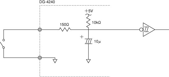
Example of Terminal Block Input Circuit and Sequencer Connection

■ Input circuits for terminal blocks HOLD, RESET, and GATE.
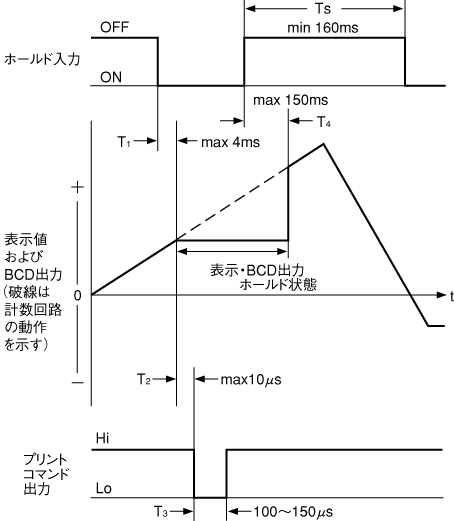
<1> Timing chart for hold input, BUSY input, and print command output
When importing data into a sequencer, please apply a hold signal to ensure that the BCD signal is captured in a stable state. Be careful, as capturing data without applying the hold signal may result in incorrect readings if the BCD data changes at the time of capture.
T1
The time from when the hold signal is input until the displayed value and BCD output data are held is up to 4ms.
T2
The time from when the displayed value and BCD output data are held until the print command signal is output is up to 10μs.
T3
The pulse width of the print command signal is 100 to 150 μs.
T4
The time from when the hold signal is released to when the hold state is released is up to 150ms.
T5
The time from releasing the hold signal to inputting again is at least 160ms. If the hold signal is input at a shorter interval than this, the print command signal may not be output.
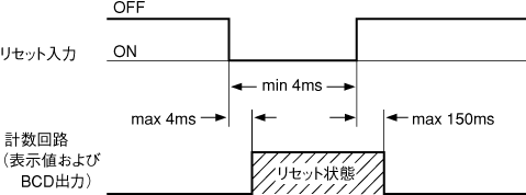
Timing Chart of Reset Signal
The pulse width of the reset input signal must be at least 4 ms. The time from when the reset signal is input until the reset state is reached is a maximum of 4 ms. Additionally, the time from when the reset signal is released until the reset state is cleared is a maximum of 150 ms.
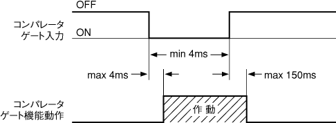
Timing chart of comparator gate input signal.
This is used to forcibly turn off the pass/fail judgment output. The pulse width of the comparator gate signal must be at least 4ms. The time from inputting the comparator gate signal to the function operating is a maximum of 4ms. Additionally, the time from releasing the comparator gate signal to the function being deactivated is a maximum of 150ms.
Last updated: 2000-12-08