

Digital Gauge Frequently Asked Questions
Question number FAQ-0061
Overview of DG-4240
The GS series gauge sensor is compatible with all GS series, regardless of new or old dimensions.
(1) Front panel
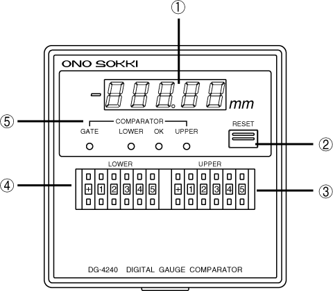
<1> Display Section
The measurement is displayed in 5-digit numbers in mm. When the measurement is negative, the "−" indicator on the left lights up. It blinks in case of a measurement error. (Please refer to the Troubleshooting section)
<2> RESET switch
When the switch is pressed, the displayed value, BCD output, and error output are reset.
<3> UPPER Digital Switch
Sets the upper limit for pass/fail judgment.
<4> LOWER Digital Switch
Sets the lower limit value for pass/fail judgment.
<5> COMPAREATOR Indicator Light
・GATE
The comparator gate signal lights up red while it is input from the <8>COMPARATOR GATE input terminal (N0.8) on the rear panel or from the <16>BCD OUT connector comparator gate input (pin 34). While lit, the forced pass/fail judgment is stopped, and all pass/fail judgment outputs are turned OFF.
・LOWER
When the count value is<4>and below the setting value of the LOWER digital switch, it lights up in red.
・OK
When the count value is <4> greater than the LOWER digital switch setting and <3> less than the UPPER digital switch setting, it lights up green.
・UPPER
When the count value is<3>above the UPPER digital setting, it lights up in red.
Back panel
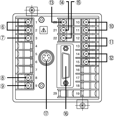
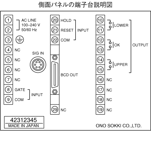
<6> Power input terminal (no.1, 2)
Inputs power in the range of AC100V to 240V.
<7> Ground terminal (No.3)
Be sure to ground it for safety and noise reduction.
<8> COMPARATOR GATE input terminal (No. 8)
If this terminal is shorted with <9> COM terminal (No. 9), the pass/fail judgment function will be forcibly stopped, and all pass/fail judgment outputs will be turned OFF.
<9> COM terminal (No. 9)
<8> is the common terminal.
<10> LOWER output relay (NO.10, 11)
It turns ON with 1 make contact output, linked to the lighting of the <5> LOWER indicator.
<11> OK output relay (No. 12, 13)
It turns ON in conjunction with the lighting of the <5> OK indicator lamp with 1 make contact output.
<12> UPPER output relay (No. 14, 15)
It turns ON in conjunction with the lighting of the <5> UPPER indicator lamp with 1 make contact output.
<13> HOLD input terminal (No.20)
Short-circuit this terminal and <15> COM terminal (No.22) to hold the displayed value and BCD output. Please note that the pass/fail judgment output is not held.
<14> RESET input terminal (No.21)
Short-circuiting this terminal and <15> COM terminal (No.22) will reset the displayed value and BCD output, as well as the error display and error output (within the BCD connector).
<15> COM terminal (No.22)
It is a common terminal for hold signal and reset signal.
<16> BCD OUT connector
It is a connector for BCD output, pass/fail judgment, and external command signals.
<17> SIG IN connector
Inputs signals from the GS type gauge sensor.
Last updated: 2000-12-08