

Digital Gauge Frequently Asked Questions
Question number FAQ-0049
Overview of DG-4120
The GS series gauge sensors will be combined with dimensional measurements. They are compatible with all GS series, regardless of whether they are new or old.
Front panel
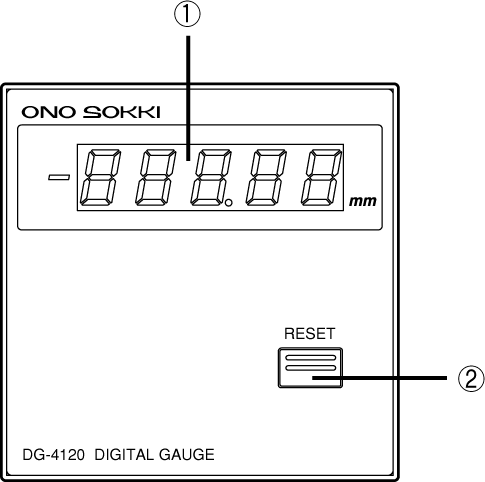
<1> Display Section
The measurement is displayed in 5-digit numbers in mm. When the measurement is negative, the "−" indicator on the left side lights up. If an error occurs in the counting section, the value will blink. (Please refer to the troubleshooting section)
RESET switch
Pressing this switch will reset the displayed value, BCD output data, error display, and error output.
Back panel
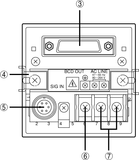
<3> BCD output connector
For more details, please refer to DG-4120 BCD out specifications.
<4> Panel mounting hardware
This is the hardware used for installing this device onto a panel.
<5> SIG IN Connector
Connect the gauge sensor signal connector.
<6> Ground terminal (terminal screw)
For safety and noise reduction, please ensure to ground at this terminal.
<7> Power input terminal
The device accepts an input power of AC100V to AC240V. The allowable power range is AC90V to AC264V.
Last updated: 2000-12-08