

Digital Gauge Frequently Asked Questions
Question number FAQ-0047
Timing chart of input signals for BCD connector
This shows the timing chart of the input signal for the BCD connector. For the pin configuration of the BCD connector, please refer to DG-4120 BCD out specifications.
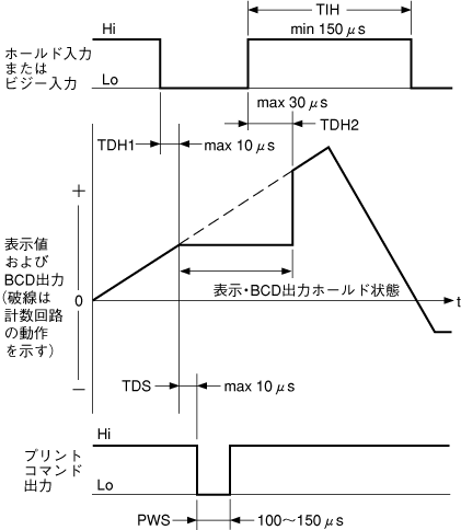
Timing chart for hold input, BUSY input, and print command output
When importing data into sequencers, etc., please input the hold signal so that the BCD signal is captured in a stable state. If you capture without inputting the hold signal, please be aware that when the BCD data is captured at the timing of being updated, it may not be read correctly.
THDH1
The time from when the hold signal is input until the displayed value and BCD output data are held is up to 10μs.
TDH2
The time from when the hold signal is released to when the hold state is released is up to 30μs.
TDS
The time from when the displayed value and BCD output data are held until the print command signal is output is up to 10μs.
PWS
The pulse width of the print command signal is 100 to 150 μs.
TIH
The minimum time from releasing the hold signal to re-entering is 150μs. If the hold signal is input at a shorter interval than this, the print command signal may not be output.
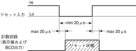
- Timing chart of the reset signal
The pulse width of the reset input signal needs to be more than 20μs. The time from inputting the reset signal to entering the reset state, as well as the time from releasing the reset signal to exiting the reset state, both require a maximum of 20μs.
Timing chart of print command output.
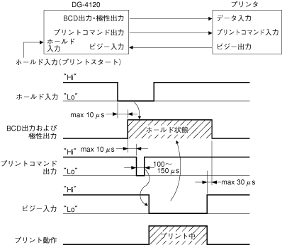
The above figure shows the case when the printer is started with the rising edge of the print command signal. The hold input should remain at a low level until the BUSY input goes low. Please input the BUSY signal to indicate that the printer is currently printing. Any hold signal input during printing will be ignored.
Last updated: 2000-12-08