

Digital Gauge Frequently Asked Questions
Question number FAQ-0046
Connection with BCD OUT sequencer
This shows the recommended interface for connecting BCD out to external devices. You can choose between positive logic and negative logic. Please be careful.
(1) In the case of receiving by voltage
BCD output, polarity output, decimal output, error output, print command output
shows the recommended circuit for external devices and the DG4120 output specifications.
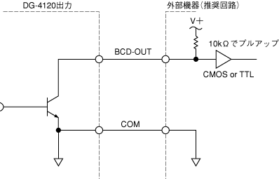
| output format | Open collector output |
|---|---|
| output IC | 74LS07 |
| withstand voltage | max 30V It is recommended to use below 24V for improved reliability. |
| maximum sink current | max 32mA |
| residual voltage | max 0.5V |
Hold input, reset input, BUSY input
shows the recommended circuit for external devices and DG4120 input specifications.
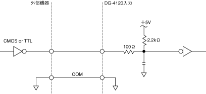
| Input low level voltage | 0~1.4V |
|---|---|
| Input Hi Level Voltage | 3~5.25V |
| input impedance | more than 1kΩ |
(2) When connecting to a sequencer
The BCDout signal is an open collector output, so please connect the sequencer side to an input unit for open collector signals (with a voltage of DC 12 to 24V).
Also, please be careful as connecting the polarity of the external power supply in reverse will damage the BCD output circuit.
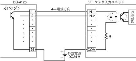
The input specifications of the DG-4120 are voltage signal inputs, so it is recommended to connect the sequencer side to a voltage output unit (such as TTL).
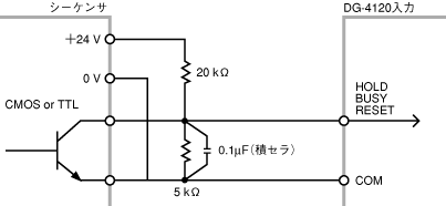
When driving with an open collector or relay contacts, there may be malfunctions due to noise depending on the environmental conditions at the site. Please implement appropriate noise countermeasures. The figure below is one example.
Recommended voltage signal input.
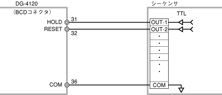
Examples of noise countermeasures
Last updated: 2000-12-08