

Frequently Asked Questions about Speedometers
Question number FAQ-0042
LC-1100/SF-660B Space Filter Detector Installation Precautions - Part 1
The "LC-1100/SF-660B space filter detector" should be installed using the included mounting fixture in a safe location with minimal engine vibrations, either at the front or rear or on the left or right side of the vehicle. Depending on the installation location, it is necessary to change the mounting direction of the detector part. By loosening the "detector fixing knob" on the holder part, it can rotate freely, so please ensure that the measurement direction is aligned with the vehicle's centerline before securing it.
1. When installing on the front and rear parts of the vehicle.
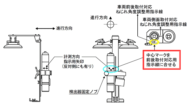
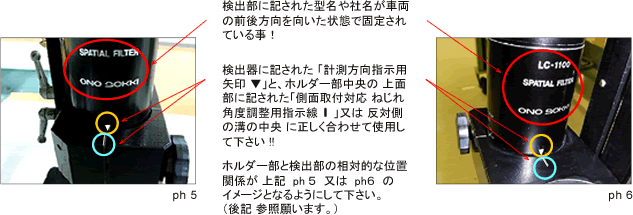
Select a location that is as perpendicular as possible to the vehicle's centerline to fix the mounting fixture plate, and then loosen the "detector fixing knob". Make sure to align the "measurement direction indication arrow ▼" marked on the surface of the detector with the "vehicle front and rear mounting corresponding twist angle adjustment indication line" on the holder part. After this, please ensure to securely tighten the "detector fixing knob" before use.
■ Specific example of the 'LC-1100 Spatial Filter Detector'
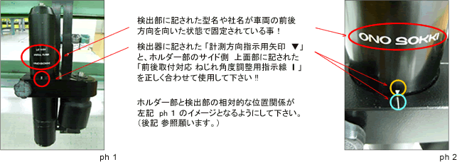
■ Example of the 'SF-660B Space Filter Detector'
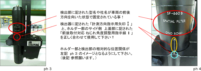
2. When installing on the side of the vehicle.
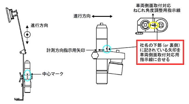
Select a location that is as parallel as possible to the vehicle's centerline to fix the mounting jig plate, and then loosen the "detector fixing knob". Make sure to align the arrow marked "measurement direction indication arrow ▼" on the surface of the detector with the "vehicle side mounting corresponding twist angle adjustment indication line" on the holder part or the groove center on the opposite side. After this, please ensure to securely tighten the "detector fixing knob" before use!!
■ Specific example of the 'LC-1100 Spatial Filter Detector'
In the case of the 'SF-660B', similar to the 'LC-1100', there is an arrow marked on the detector for indicating the measurement direction. "Please adjust the installation angle using the 'twist angle adjustment guide line for vehicle side mounting' on the holder part or the groove on the opposite side."
3. Special case for installation on the front and rear parts of the vehicle.
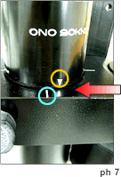
If it is absolutely impossible to make the mounting jig plate perpendicular to the vehicle's centerline due to the shape of the front and rear parts of the vehicle, please slightly shift the "measurement direction indication arrow ▼" marked on the detector, as seen in ph7, from the "twist angle adjustment indication line" so that the line connecting the measurement direction indication arrows marked on the front and back is parallel to the vehicle's centerline.
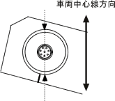
<Warning>
Please use this method only as a last resort, as it can easily cause measurement errors. After completing the measurement, be sure to realign the marks above.
4. "LC-1100/SF-660B Spatial Filter Detector" Installation Position and Relationship with Illumination
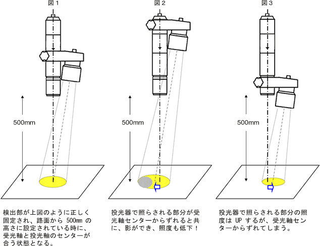
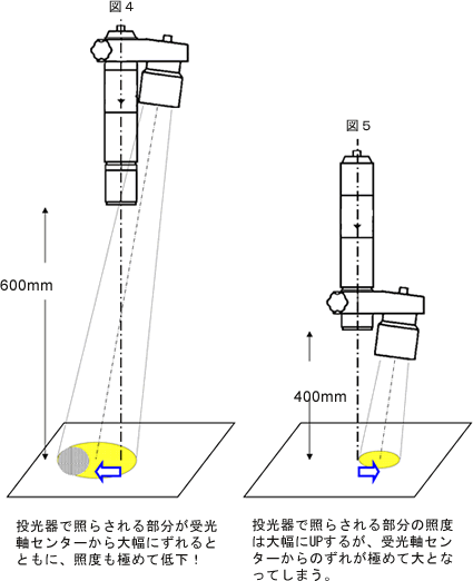
The LC-1100/SF-660B space filter detector is fixed in a position as shown in Figure 1, designed to perform at its best when in use. If fixed at the rear end as seen in Figure 2, only the light-emitting part will be displaced, resulting in a significant "shift" from the center of the receiving axis and a decrease in illumination. Particularly, if the entire detector is moved away from the road surface as shown in Figure 4, the illumination will drop drastically, leading to measurement failures. Additionally, if fixed at the front end as seen in Figure 3, the light-emitting part will come closer, which increases illumination, but also results in a larger "shift" from the center of the receiving axis, causing measurement failures in this case as well. Please fix it in the correct position as shown in Figure 1 as much as possible.
Also, please refer to "Notes on Installing the LC-1100/SF-660B Space Filter Detector - Part 2".
Last updated date: 2009-05-25