

Frequently Asked Questions about Fuel Flow Meters
Question number FAQ-0016
What is the initial setup method for using the FP-213/213S flow detector with the FM-2500 flow indicator?
When using the FM series for the first time, it is essential to perform the initial settings for the FP flow detector as outlined below.
Similarly, if you change the FP flow detector, the settings will also be required.
Initial setting method for using FP213/213S flow detector with FM-2500 flow indicator
Notice
- This is the method for setting standard specifications. Please note that the settings differ for custom specifications.
- This is the setting method from factory shipment.
- This is a setting for measuring instantaneous flow (volume). For settings related to other measurements, please refer to the instruction manual.
- The display update time is set to 1 second (factory default). For changes, please refer to the instruction manual.
(1) Set the date. (※Not necessary if the date is correct) →Click here for the setting method
(2) ① Set the detector, ② set the factor value, ③ set the encoder pulse in order.
Operating Instructions
1.  Press (MENU) to display the settings screen.
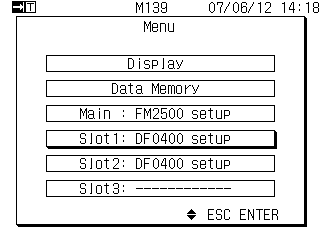 |
Please select the slot to use. If using multiple, each requires configuration.
|
 select
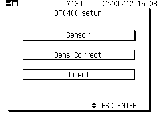
The 2.DF-0400 Setup menu will be displayed.
 |
|
 select
3. The sensor setup menu will be displayed.
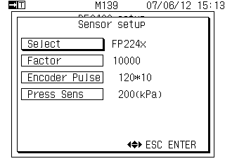 |
 or or at at select select Press to display the detector selection list. Press to display the detector selection list. |
4. Display the list of detectors to be set.
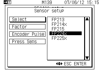 |
>> Select the detector to use
|
5. Specify the detector to be used.
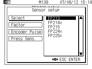 |
orSelect FP213Pressing this will confirm the settings of the detector. |
Set the factor value.
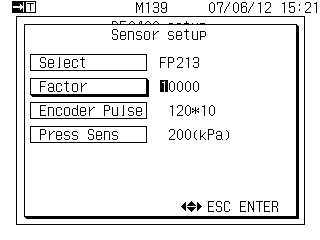 |
Set the factor values as indicated on the detector's nameplate or in the inspection report. |
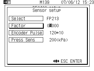 |
|
 select,
 or
or Pressing it will move the inverted digit.
[Example of a 4-digit factor value]
If the factor value is 4 digits, set the highest digit to 0: 09824 (example setting)
7. Determination of factor values.
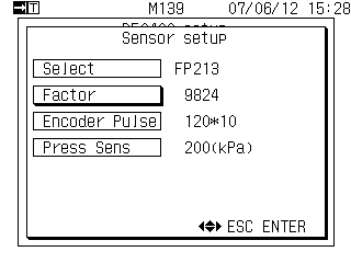 |
Pressing this will confirm the setting of the factor value. |
Setting of Encoder Pulses
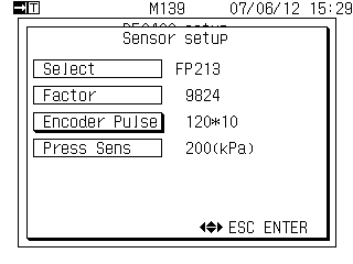 |
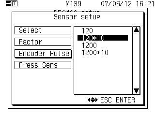
If the encoder pulse is displayed (set) as 120*10, no settings are required. If it is set (displayed) to something other than 120*10,
|
 select
Select from the list.
 |
|
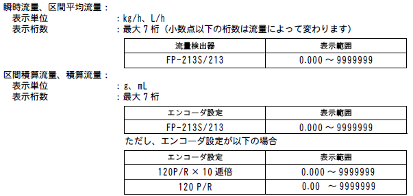
The number of decimal places will be from 0.000 to .
*If you want to reduce the number of digits by 1, please select 120.
10. Pressing it will bring up the measurement display screen.
 This is the setting of the rated pressure for the pressure sensor.
No pressure sensors are used, so no settings are necessary. (The factory settings are fine as they are.)
Last updated: June 18, 2007