

Crank Angle Detector - Frequently Asked Questions
Question number FAQ-0001
CA-500A Offset Adjustment Method
Adjust the offset volume to correctly output 1P/R, 720P/R, and 360P/R pulse signals. It is recommended to adjust the volume while checking the waveform with an oscilloscope or similar device.
(1) MONITOR output
Rear panel
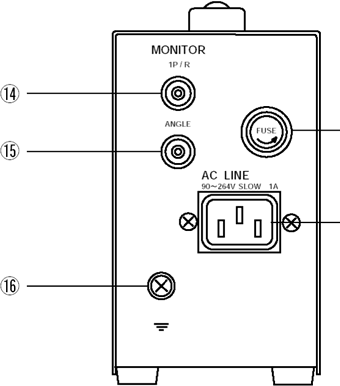
⑭ 1P/R
⑮ ANGLE
This connector outputs the input signals from the CP-5100 and CP-5200 detectors. By observing this waveform, you can check whether the detector is functioning correctly. The operating waveform for the CA-500A is shown in Figure 1. Depending on the situation, such as fiber optic cable connections, the maximum voltage is ±15V. If the amplitude is smaller than that shown in Figure 1, the CP detector needs to be inspected.
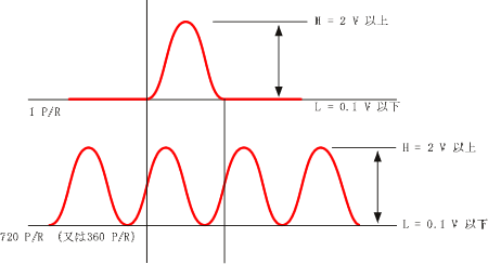
Figure 1
(2) Pulse output 1P/R, 1/1, 1/2 output connector
Front panel
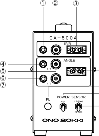
① 1P/R pulse output LED
② 1P/R pulse output connector
④ ANGLE pulse output LED
⑤ ANGLE pulse output
⑥ 1/2 ANGLE pulse output LED
⑦ 1/2 ANGLE pulse output connector
A signal of 1 pulse per revolution is output from ②, causing LED ① to blink. An ANGLE signal (e.g., 720P/R) is output from ⑤, causing LED ④ to blink. The signal from ⑤ is halved (e.g., 360P/R) and output from ⑦, causing LED ⑥ to blink. (If the signal frequency is fast, it will appear almost constantly lit.)
(3) Adjustment of OFFSET
■ 1P/R pulse output
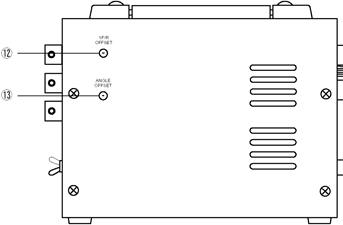
⑫ 1P/R OFFSET Volume
⑬ ANGLE OFFSET Volume
The 1P/R input signal has a DC component superimposed on it as shown in Figure 2 by turning the ⑫1P/ROFFSET volume. The pulse output threshold is 0V. The pulse is output at the timing shown in Figure 2. Run the engine at a suitable RPM, first turn the OFFSET volume all the way counterclockwise (applying a positive voltage offset), and then slowly turn it back counterclockwise until LED ① lights up. Turning it further will turn the LED off. Adjust it so that a stable waveform is output.
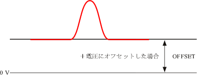
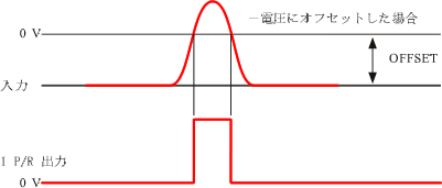
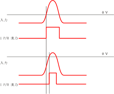
Figure 2
■ ANGLE pulse output
Similar to the 1P/R setting, adjust the ⑬ANGLEOFFSET volume so that the pulse width is output stably as shown in Figure 3. For example, turn on the ④LED when you have confirmed that 720P/R is being output correctly for one rotation. Turning the OFFSET volume all the way clockwise applies a positive voltage offset.
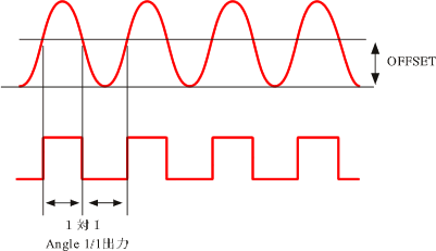
Figure 3
(4) Timing of 1P/R and ANGLE pulse output
As described in section (3), the pulse width changes depending on the adjustment of the OFFSET volume. Monitor the 1P/R pulse and the ANGLE pulse simultaneously and check the timing of each. If the rising (or falling) of the 1P/R pulse and the rising (or falling) of the ANGLE pulse coincide, it may cause a malfunction, depending on the requirements of the connected device such as a combustion analyzer. Therefore, fine-tune the 1P/R OFFSET volume to slightly offset them as shown in Figure 4. ④This can also cause the LED to not blink.
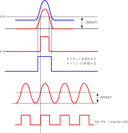
Figure 4
Last updated: 2002-09-17