The linear gauge consists of a linear gauge sensor (detector) and a digital gauge counter (display).
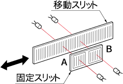
The linear gauge sensor has a moving slit that moves in conjunction with the spindle and a fixed slit that is fixed in a certain position, arranged opposite each other. The slits have alternating light and dark scales printed at regular intervals. Since it is necessary to determine the direction of spindle movement (+, - direction) for counting, the two fixed slits A and B are positioned such that B is offset by 1/4P (pitch) relative to A.
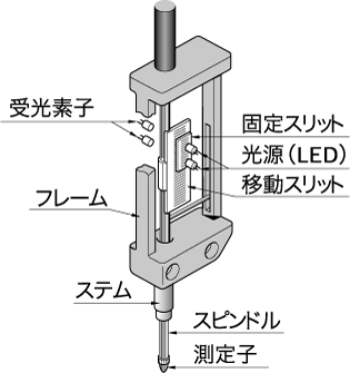
Between these slits, a light source (LED) and a light receiving element face each other. (Figure 1)
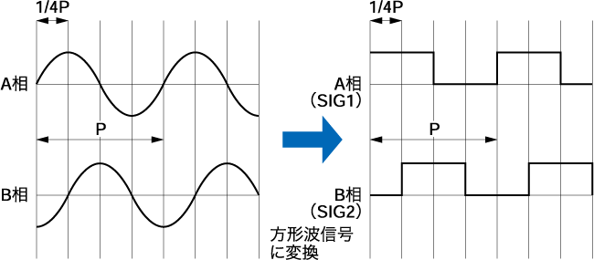
As the moving slit moves relative to the fixed slit, the light passing through the window of the fixed slit alternates between light and dark. At this time, two square wave signals with a phase difference of 90° are output at the same period. The direction is determined from the advance or delay of the phase, and counting is performed by addition or subtraction in the counter to measure the displacement amount. (Figure 2)
The output signal of the linear gauge sensor is 1P (pitch) = 4 μm (1 μm resolution type) or 1P (pitch) = 40 μm (10 μm resolution type), but by multiplying by 4 in the digital gauge counter, a measurement resolution of 1/4 of 1P (pitch) (1μm or 10μm) is obtained.