

Torque Meter Frequently Asked Questions
Question number FAQ-1303
How to set up the TS-2600 N-0
To set N-0, use terminal mode.
Terminal mode
The DEC VT-100, a dedicated terminal device, is supported as a standard terminal in many minicomputers and workstations. The TS-2600 can enter full screen terminal mode by utilizing the escape sequence available for the VT-100 terminal.
(Note) For information on starting terminal mode, please refer to "How to start terminal mode" in the questions section, and for parameter settings, please refer to the "Setting Procedure Manual".
 Function and operation key description
Terminal mode has two modes: Monitor mode and Set mode. In Monitor mode, the torque, rotation value, and switch status are displayed for each gate time. In Set mode, the torque zero correction value and N-0 correction value can be set. The figure below shows the screen when Terminal mode is opened.
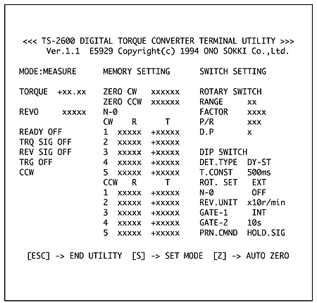
1. Monitor Mode
| 「ESC」 | Terminal mode ends |
| 「S」 | Enter set mode |
| 「Z」 | Perform zero torque correction in the currently set rotation direction. |
2-set mode
| 「ESC」 | Exit set mode and return to monitor mode. |
| 「BS」「DEL」「←」 | Delete one character |
| 「+」「−」 | Sign input (valid only when N-0 correction value is set) |
| 「0 」~「9 」 | Numeric input |
| 「ENTER」 | To navigate between settings and confirm settings, if you make a mistake in the input value, you need to keep pressing the "ENTER" key to cycle through the settings. |
| 「!」 | The N-0 setting values are sorted (sorted in ascending order of rotation) and the table calculations are performed and stored in backup memory. (If parameter setting is ON, the correction is enabled). At this time, the zero correction value for torque is also written to backup memory. |
3. Common key operations in both modes.
| 「CTRL 」+「L」 | Redraw the screen (press the "CTRL" key and then the "L" key) |
How to input N-0 correction values
Enter the recorded data in "Input of detector frequency response (N-0) correction value".
(See (1) Preparation of N-0 correction value below) On the terminal screen, R represents rotation and T represents torque value.
1. Press "S" to enter set mode.
2. Use the "ENTER" key to move between items and enter the rotation and torque values.
3. Press "!" to save to backup memory.
4. Input of the detector frequency response (N-0) correction value.
Due to the frequency characteristics of the detector, torque measurements may appear even when the shaft is rotating under no load.
This value is reproducible, so by setting a correction value for each rotation speed, high-precision measurements are possible. Turn OFF parameter settings 1-4.
(1) Preparation of N-0 correction values
Prepare a table like the one below, which shows the rotational speeds within the measurement range.
| Rotational speed (r/min) | 0 | 1000 | 2000 | 3000 | 4000 | 5000 |
|---|---|---|---|---|---|---|
| Torque count | 2 |
[Note] In the count field, enter the number without displaying the decimal point. <Example: 0.02 → 2>
With the detection axis unloaded (nothing attached to one side of the axis), rotate it using a motor or similar device and record the torque display value for each rotational speed. If using both CW/CCW, create a test for both directions.
This device can accept 5 input points each for CW and CCW. Linear approximation is performed between input points to correct for points other than the input points. It is also possible to record finely around areas with large numerical changes and coarsely around areas with small changes.
Example: Rotation speed → 500, 1000, 1500, 2000, 5000
(2) Input of N-0 correction value
This is done by connecting via RS-232C. For details, please refer to the question "Starting the Terminator".
(3) Turning parameter settings 1-4 in the internal settings section ON enables the setting of N-0 correction values.
(4) By turning the TEST switch (parameter setting 2-3) ON and setting the MEAS/CAL switch to CAL, you can check the N-0 correction value setting.
How to check N-0 settings
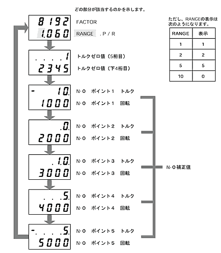
The CAL function displays the FACTER and N-0 setting values on the torque and rotation displays.
(Note) Parameter settings are required. For details on setting parameters, please refer to the "Setting Procedure Manual".
1. Parameter setting 2. Turn ON pin 3 of the 4-bit DIP switch.
2. The TEST switch (parameter setting 2-3) sets the MEAS/CAL switch to CAL.
3. By pressing the TRQ ZERO switch, the torque display and rotation display will change sequentially as shown in the diagram below.
(Torque indicator: Torque factor, etc.; Rotation indicator: Torque range, etc.)
<Notes on the display>
|
Last updated: 2002-03-15