

Torque Meter Frequently Asked Questions
Question number FAQ-1302
TS-2100 Voltage Output
We will now explain the voltage output. Please refer to the "Setting Procedure Manual" for information on setting the parameters.
1. Torque voltage output
The torque is output as an analog voltage from the TRQ OUT connector on the rear panel. Depending on the torque sensor's RANGE setting, the output voltage during full-scale measurement will be as follows:
| Detector RANGE | Output voltage at full scale |
|---|---|
| 1 | ±1 V |
| 2 | ±2 V |
| 5 | ±5 V |
| 10 | ±10 V |
Output connector: C02 type (BNC) connector
Recommended load: 10 kΩ or higher. Time constant: 500 ms, 100 ms (switchable).
Turning the parameter setting DIP switch 8 in the internal settings section ON will set the response time to 100 ms. It is set to OFF by default.
 How calibration the torque voltage output
This will be done while monitoring the display of a digital multimeter (hereinafter abbreviated as "digital multimeter"). Please have a digital multimeter ready.- When making adjustments, ensure that neither one nor both axes of the detector are connected to any other equipment to avoid putting any load on the axes.
- Power the detector and set the toggle switch to match the direction of rotation. Confirm that the TRQ SIG LED on the TS-2100 is lit.
- Connect the TRQ OUT terminal on the rear panel to the digital voltmeter.
- Measure the output voltage under no load; if it is 0 V, no adjustment is necessary. If there is a discrepancy in the output voltage, change the TRQ ZERO digit switch on the front panel. Do not touch the ANALOG ADJ TRQ ZERO potentiometer. (Use ANALOG ADJ TRQ ZERO only if there is a difference between the output voltage and the BCD output.)
- When the value calculated from the TRQ ZERO digit switch setting is set, the output state for full-scale measurement is activated, and the digit volt display value will be as follows.
Detector RANGE TRQ ZERO Digivolt display value 1 1000 1 V 2 2000 2 V 5 5000 5 V 10 10000 - If there is a discrepancy in the displayed value, adjust it by turning the TRQ FULL potentiometer on the front panel.
- Please reset the TRQ ZERO value to its original value before starting the measurement.
2 rotations of voltage output
<Please note>
Please note that even within the input frequency range, the output will only go up to 10 V = 10,000 r/min. The lower frequency limit, when converted to rotational speed, corresponds to 20 r/min at 60 P/R, 10 r/min at 120 P/R, and approximately 6.6 r/min at 180 P/R.
The rotational speed is output as an analog voltage from the REV OUT connector on the rear panel. Set the P/R switch in the internal settings section to match the number of teeth on the rotation detection gear. At 10000 r/min, 10 V will be output.
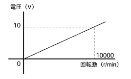
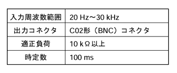
Normally, the device measures and outputs the input signal to the REV IN connector on the rear panel. By turning on DIP switch 1 for parameter setting in the internal settings section and rotating the motor attached to the torque sensor, you can produce an output proportional to the rotation speed. However, even when the shaft is stationary, there will be an offset output equal to the number of rotations of the attached motor. Please note that this offset varies depending on the sensor and changes over time.
How calibration the rotational voltage output
- Stop the rotation of the detector axis.
- Connect the REV OUT terminal on the rear panel to the digital voltmeter.
- When you turn on the DIP switch 3 for parameter setting in the internal settings section, 0 V will be output. If it does not output 0 V, adjust it by turning the REV ZERO potentiometer on the front panel.
- Turn on the 4th DIP switch for parameter setting in the internal settings section. The following voltages will be output according to the scale of the P/R switch in the internal settings section. If there is a voltage discrepancy, adjust it by turning the REV FULL potentiometer on the front panel.
P/R Set scale Output voltage 60 P/R Scale 1 10 V 120 P/R Scale 2 5 V 180 P/R Scale 3 3.3 V - Please return the parameter setting DIP switches 3 and 4 on the internal settings section to OFF before starting the measurement.
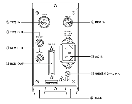
Voltage output terminal (rear panel)
Connector Name
TRQ OUT: Torque output
REV OUT: Rotation output
Last updated: 2002-03-15