

Torque Meter Frequently Asked Questions
Question number FAQ-1267
Coupling and alignment work
Please select a coupling that is suitable for the torque capacity. Recommended couplings are listed in the torque meter catalog and torque detector instruction manual, so please refer to them. Also, please refer to the Torquemeter FAQ, "What is the alignment accuracy, and what kind of coupling is best?"
Eccentricity can affect torque measurement. It can also cause abnormal vibration and noise, leading to malfunctions. While couplings have an eccentricity tolerance, for the SS series, ensure the eccentricity is within 5/100 mm (TIR = Total Indicator Reading - the difference between the maximum and minimum measured values). The required alignment accuracy is specified in the torque sensor's instruction manual.
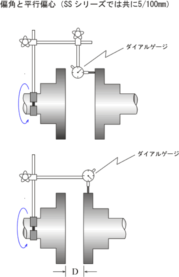
The torque sensor alignment process is performed while checking for eccentricity, as shown in the following diagram. By inserting shims between the torque sensor and the mounting base and adjusting the height left and right, the axis of the torque sensor is aligned with the axis of the motor, etc. For detailed installation instructions, please refer to the coupling manufacturer's instruction manual and other documents. Vibrations due to imbalance will occur at high rotational speeds. When performing this work, please seek guidance from someone experienced in the installation of rotating machinery.
The following is an overview of the coupling installation process (please contact the coupling manufacturer for further details).
- Check that there are no burrs on the shaft or hole, and verify that the key fits properly to the shaft and coupling hub.
- Attach the coupling hub to the shaft.
- The mechanical device and torque sensor are aligned so that they can be connected using the shaft end dimensions specified for the coupling.
- Declination adjustment:
Secure the dial gauge to one side of the coupling hub and place the dial gauge probe against the opposite side of the coupling hub (the side being measured). Rotate the hub on the side where the dial gauge is fixed 360 degrees and reset the display to zero at the smallest reading position of the dial gauge.
Rotate the hub 360 degrees again and insert shims between the torque sensor and the mount to adjust the tilt so that the dial gauge deflection is within 5/100 mm (TIR) in the case of the SS series.
- Parallel eccentric adjustment:
Secure the dial gauge to one side of the coupling hub, and place the dial gauge probe against the outer circumference of the opposite coupling hub (the side being measured). Rotate the hub on the side where the dial gauge is fixed 360 degrees and reset the display at the minimum reading position of the dial gauge. Rotate the same hub 360 degrees again and, in the case of the SS series, insert shims between the torque sensor and the mount to adjust the height on both sides so that the deflection of the dial gauge is within "5/100 mm (TIR)", and then temporarily fix the torque sensor in place. After that, recheck the deflection angle. - Assemble the coupling and connect the shafts.
- Securely fasten the torque sensor.
- For future maintenance, knock pins may be added to the base of the torque sensor.
Last updated: 2008-09-24