

XN-8000 Frequently Asked Questions
Question number FAQ-1120
The method of calibration with a sound level meter using an audio calibrator is
When using a sound level meter to perform frequency analysis of noise with the XN-8000 series, calibration with the sound level meter is conducted to set the Y-axis to the sound level meter's dBspl. For example, during calibration, a reference sound pressure of 124 dBspl is input from an acoustic calibrator into the sound level meter, and the AC out signal from the sound level meter is used in the XN8000 series 'calibration' dialog, at which point the sound level meter will be in the '130 dB' range. If the '130 dB' range is too large for measurement, the '80 dB' range will be used for calibration following the next steps.
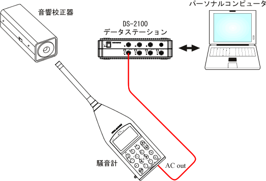
Figure 1 Configuration Diagram
Flow of operations
- Open the "calibration" dialog
- Execute the "calibration by calibration → Reference Signal"
- In the "Channel: Signal Input" dialog, set the measurement range of the sound level meter.
■ Operating Procedures
- Open the 1ch FFT analyzer project. For project creation, please refer to the "1chFFT Project Creation Manual".
- Insert the sound level meter into the audio calibration device and input the reference sound pressure "124dBspl".
- Click the [Config Board] button to open the 'Config Board' dialog. (See Figure 2 below)
- Click on 'ch1' of the 'Channel Palette' to display the analysis configuration diagram on the config board. (See Figure 2 below.)
Click the [CAL] button to open the "calibration" dialog. (See Figure 3 below)
Click [calibration with reference signal] in the "calibration" dialog to open the calibration window. The spectrum of reference sound pressure will be displayed in the window. (See Figure 3 below)
Screen of the "calibration by calibration → Reference Signal" dialog
→: Indicates items that require configuration.
Red circle: calibration Indicates items that are automatically displayed when a task is performed.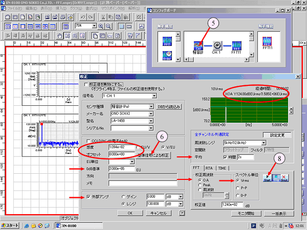
Figure 3- Select and set each item within the "calibration" dialog as shown in Figure 2. (Arrow → in Figure 3)
0dB reference 2.000e-5 (20μPa) external amplifier Check on Rejiji “130 dB” frequency range 5kHz
(You can change it by turning on the [Settings] button)average Check on and set the time as desired
(You can change it by turning on the [Change Settings] button)calibration frequency Overalls spectrum unit Vrms calibration value Set the reference sound pressure value for the "124" acoustic calibration device - Click the [START] button in the "calibration" dialog. When the average time is finished, the "X:OAY:124.00" and "Sensitivity" sections automatically calculate and display the "Constant to convert to 124 dB display." (Figure 3, red circle)
- Click the [OK] button to finish calibration the process.
- Remove the audio calibration device from the sound level meter.
- Change the range of the sound level meter to '80dB'.
- Click the button to open the "Channel: Signal Input" dialog. (See Figure 4 below)
"Channel: Signal Input → External Amplifier" dialog screen
Red circle: Indicates items related to the explanation.
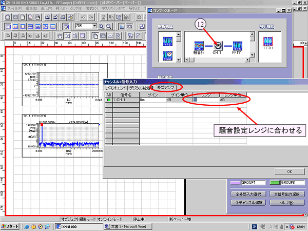
Figure 4 - Open the page for 'external amplifier'. (Figure 4)
- Set the related items as follows. (Figure 4)
- Click the [OK] button.
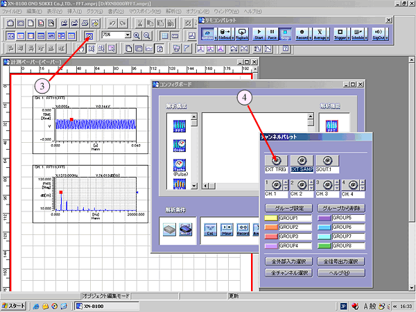
Figure 2
| range | 80 dB |
| range unit | dB |
With that, calibration is finished. You can now start the measurement.
If you change the range of sound level meter, operate from (11) to (15) again.
Last updated: August 21, 2006