

CF-5200 Frequently Asked Questions
Question number FAQ-0366
Measurement of open-loop transfer function using the CF-0510 summing amplifier
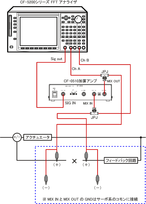
■Wiring method
The wiring for measuring the open-loop transfer function (loop transfer function) using the CF5200 + CF0510 summing amplifier is shown in the diagram below.
|
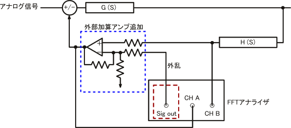
■ Block diagram
|
■Measurement method
Connect the CF-0510 summing amplifier as shown in the diagram above.
A sine sweep signal is injected as a disturbance into the summing amplifier, and the frequency response function FRF12 (ch B/ch A) is measured. Care should be taken with the amplitude of the sine waveform to avoid abnormal resonance. The analog signal (command signal) is kept constant.
The measured transfer function FRF12 is due to negative feedback;
|
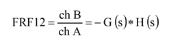
This is how it works. The minus sign (-) indicates a phase shift of 180 degrees, so if you want to see the remaining gain with the FRF12 data as is, you will be reading the gain at a phase of 0 degrees.
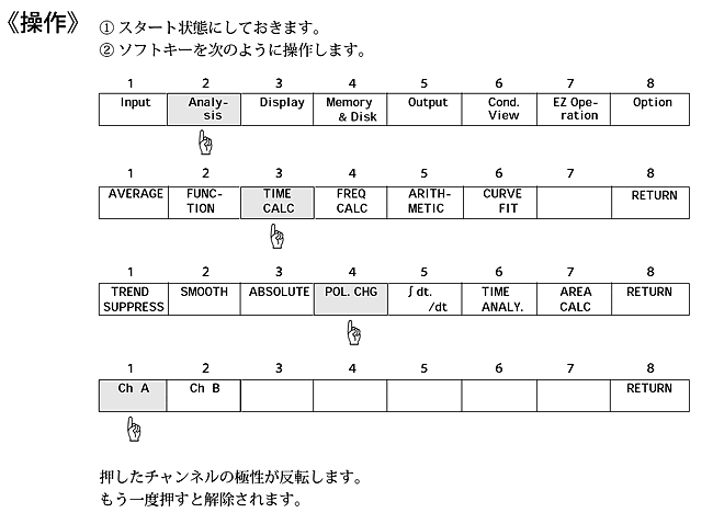
To invert the phase by 180 degrees and display G(s)*H(s), you can invert the polarity (shift it by 180 degrees) of either the ch A or ch B signal. Please refer to "Operating Polarity Inversion on the CF-5200" below for instructions.
■Operating polarity reversal on the CF-5200
The polarity of only ChA is reversed, and the frequency response function is measured.
|
For instructions on how to perform servo analysis, please refer to the following page.
Last updated: 2009-08-24