本文にスキップする

Select your region & language

Global

Region

O-Solution Field Balancing OS-0551
Making balance correction for rotating machinery easy for everyone. Start here to uncover the causes of abnormal vibration.

Among the causes of abnormal vibration in rotating machinery, it is said that "unbalance" is the most common. Correcting this balance (changing weight positions, adding weights, cutting, etc.) has traditionally been a manual task involving complex calculations, requiring a significant amount of time as it relied on individual experience and intuition.
The combination of DS-5000 hardware and OS-0551 Field Balancing overcomes this challenge. It simplifies and standardizes balance correction work, creating an environment where anyone can perform high-precision corrections easily and in a short time, even without specialized experience.
Furthermore, by combining it with other optional functions such as frequency response analysis and tracking analysis, it helps in investigating and clarifying the fundamental root causes of vibration problems as a "whole."

characteristics

Added a grinding wheel mode in addition to the conventional rotor mode.

In addition to the rotor mode of the conventional DS-0227 model, the OS-0551 field balancing also supports balance correction using the balance pieces of rotating grinding wheels.

Rotor mode

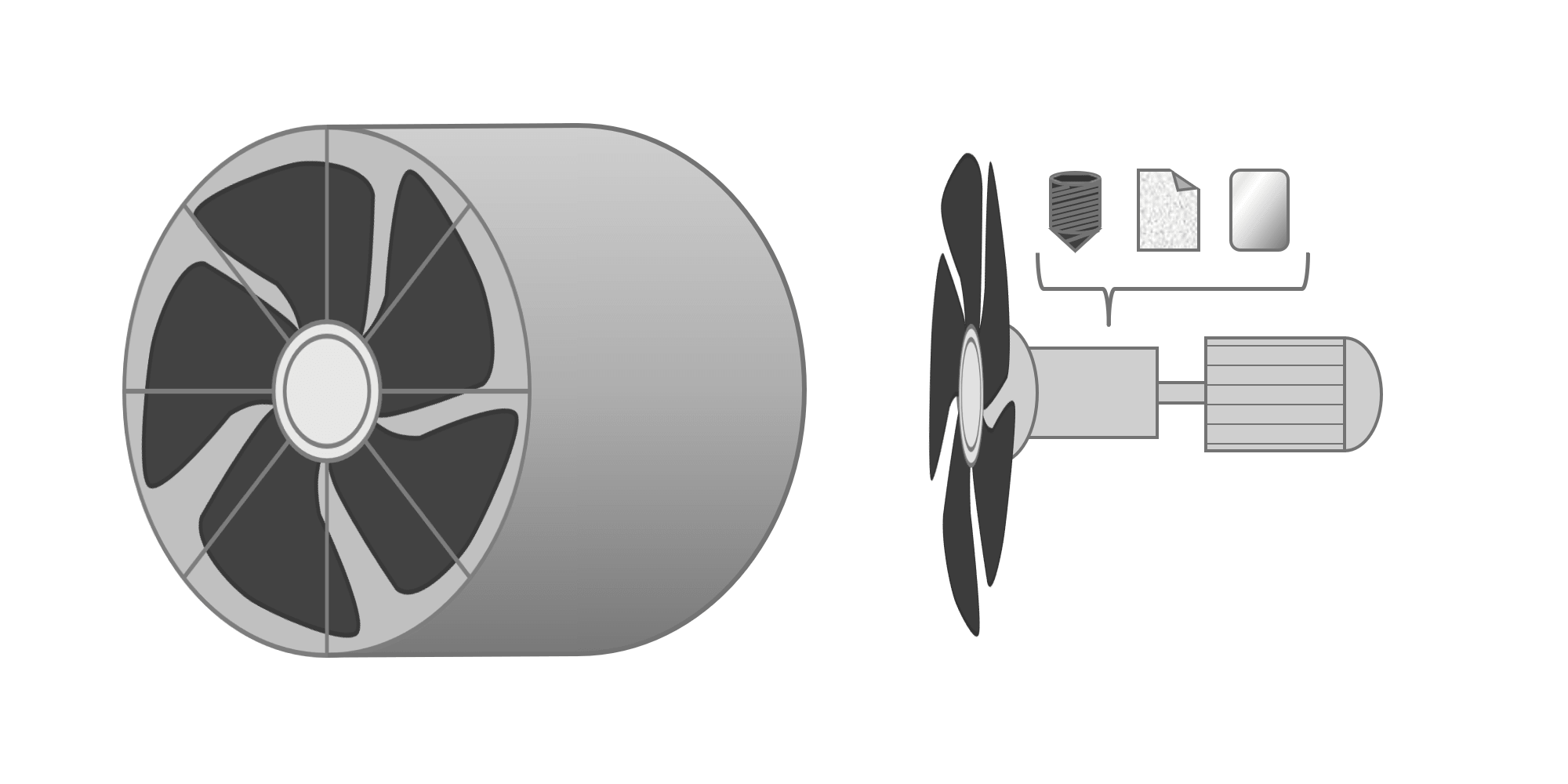
Balance correction can be performed on a rotating body supported by bearings by adding weights or by shaving the object.

  • Rotor Mode No. 1
  • Rotor Mode No. 2
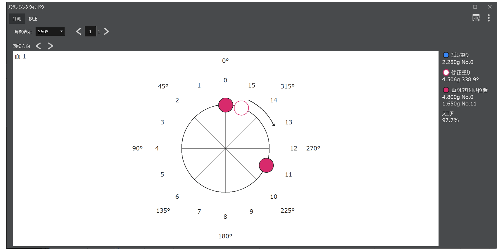
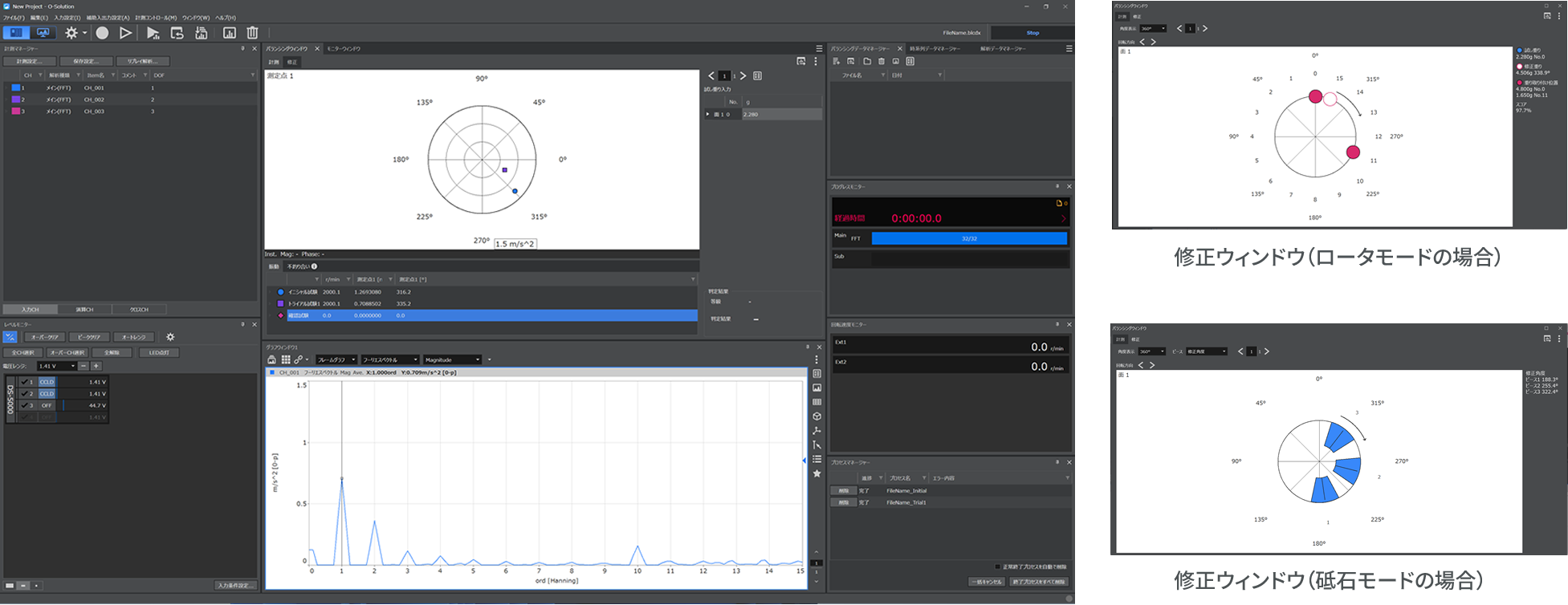
    Rotor Mode Correction Screen

Sharpening mode

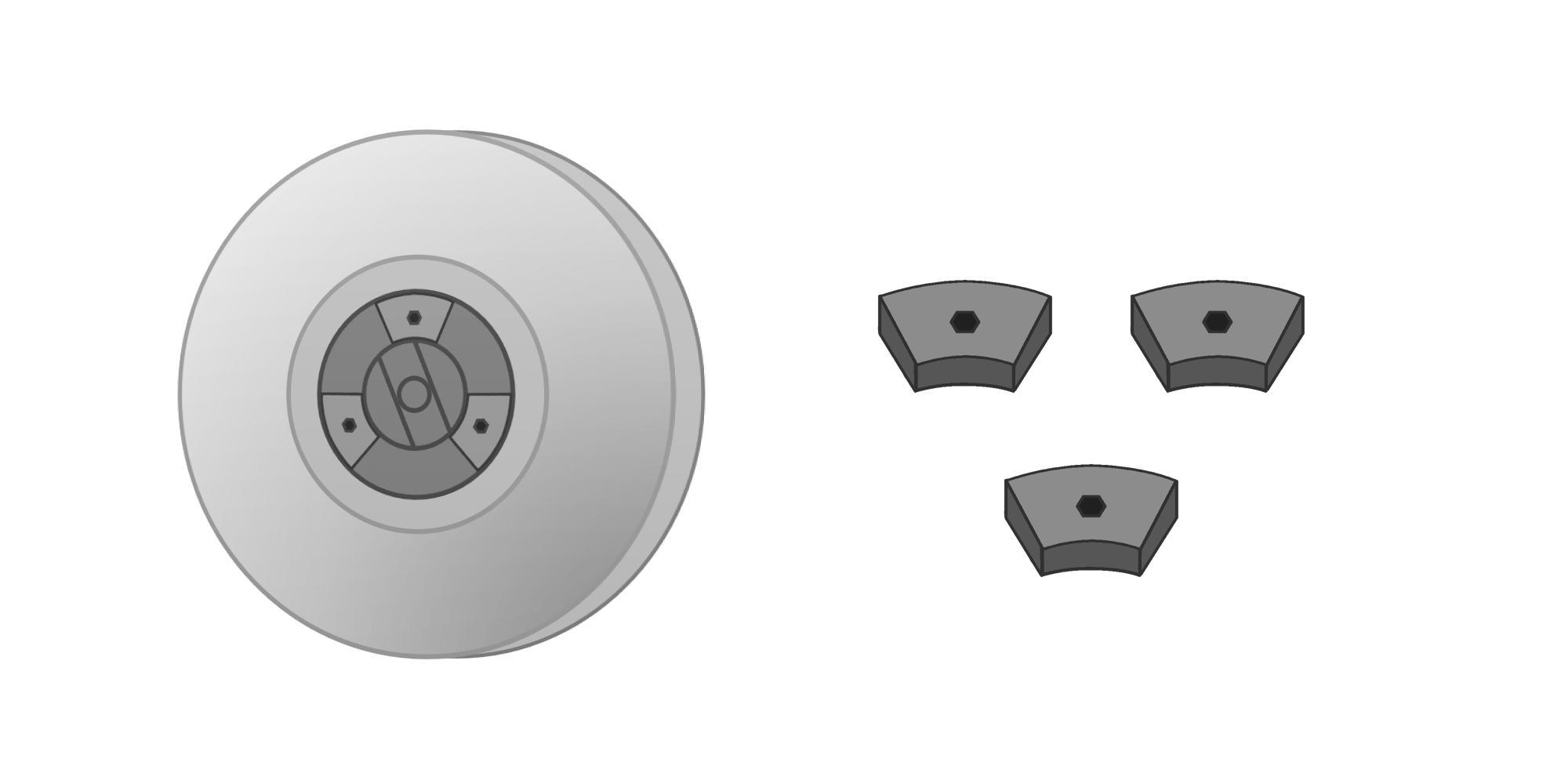
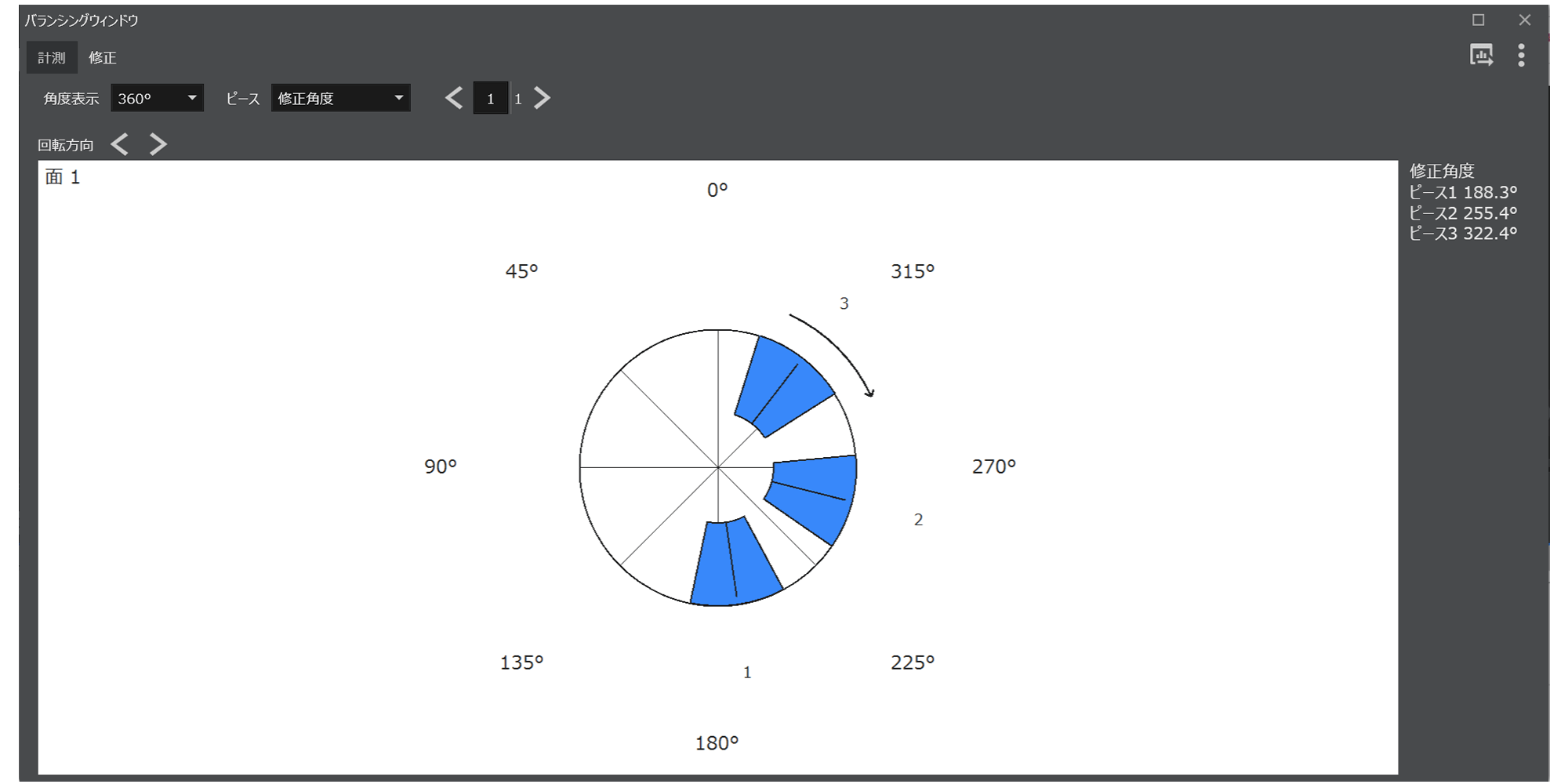
Balance correction can be performed using the balance pieces of the grinding wheel.

  • Grinding Stone Mode No. 1
  • Grinding Stone Mode No. 2
    Grinding Stone Mode Correction Screen
Supports high-speed rotating bodies. Capable of analyzing up to 260,000 RPM.

In recent years, the speed of various rotating bodies has been increasing. By taking both hardware and software approaches to accommodate the balancing of industrial equipment motors and E-Axles in EVs, we have achieved compatibility with high-speed rotations of up to 260,000 r/min.

Pre-registration function for correction weights

It is not a problem if you cannot provide the exact weight specified during balance correction. By registering your available weights in advance, the system will calculate and suggest a balance correction using combinations of those weights. Additionally, taking the ideal weight correction as 100%, you can check a score indicating how effectively your pre-registered weights can perform the balance correction.

Correction position division function

If a correction hole is not drilled exactly at the specified position during balance adjustment, or if a fixing screw is already present at the correction position, you can specify the correction position using equal or unequal division. By specifying the division of the correction position in advance, the system performs calculations to ensure that the correction weights are attached at positions according to those specifications.

Judgment functions based on JIS standards and warning display functions for dangerous situations.

It can display balance quality grades as defined in JIS B0905:1992 and provide warning displays in the event of excessive vibration caused by trial weights.

System Configurations

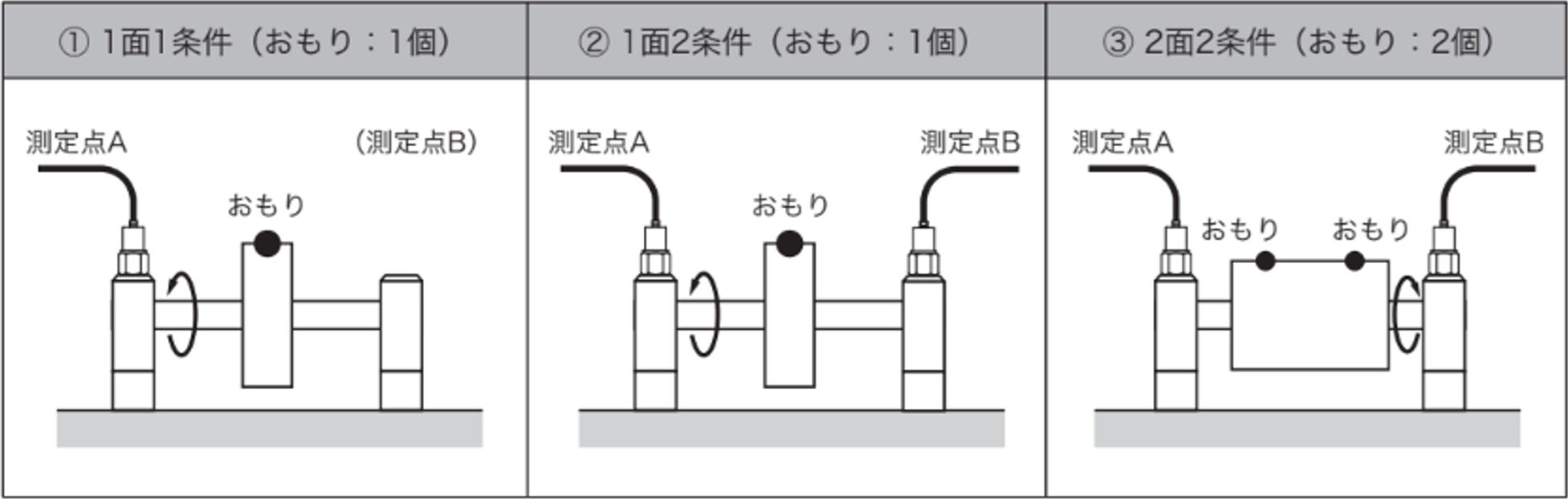
Regarding the number of surfaces to be corrected and the conditions

The plane where balance correction is performed by attaching correction weights, cutting (removing) unbalanced parts with a drill, or moving balance pieces is called the "correction plane."
The correction plane can be limited to one plane (1-plane correction) or may require two planes to be set (2-plane correction). Generally, thin disc-shaped rotors can be handled with 1-plane correction, but rotors that are long in the axial direction require 2-plane correction.

The condition refers to the number of locations where vibration is measured (number of measurement points). Usually, the number of measurement points is either 1 or 2.
If there are 2 measurement points, the measurement data from both points is captured, and a balancing correction calculation is executed to simultaneously reduce the vibration at both locations.

  • Number of correction surfaces and conditions

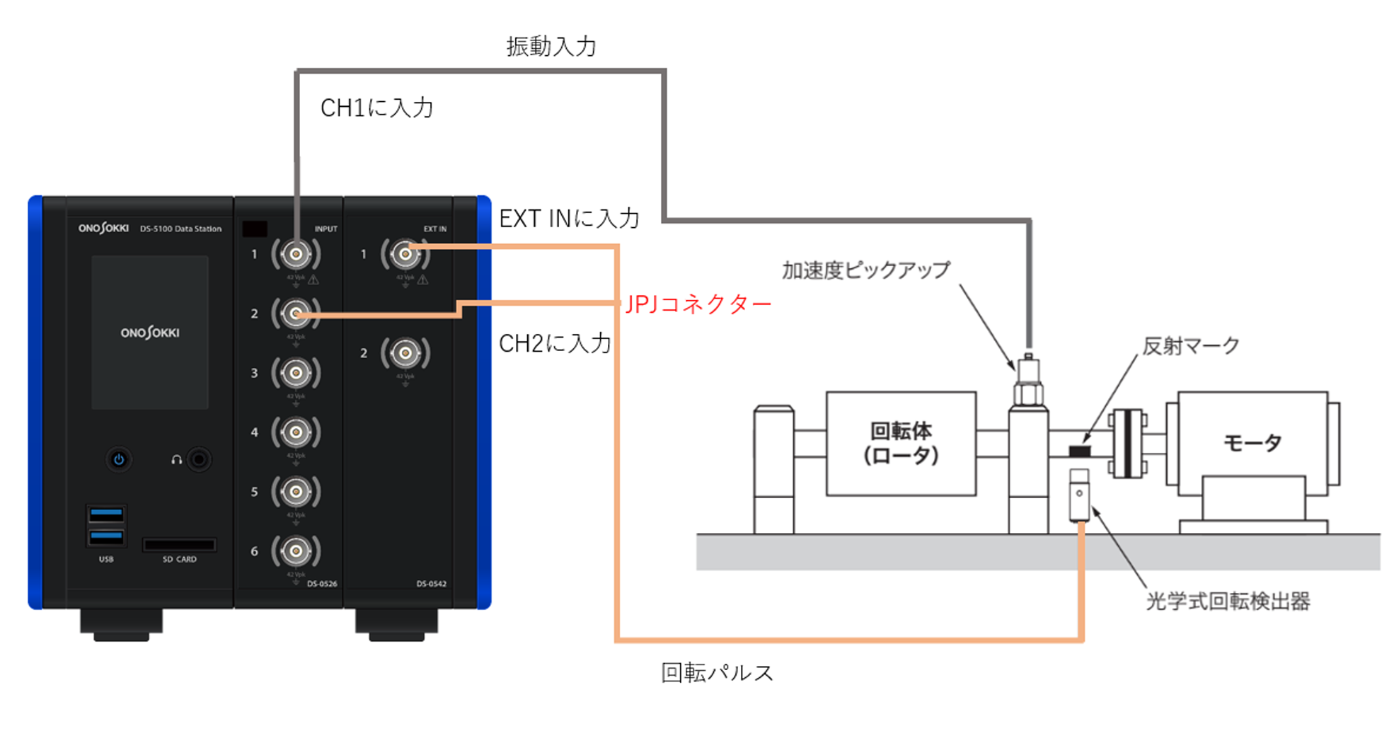
System configuration example for one side and one condition

  • System configuration example for one side and one condition

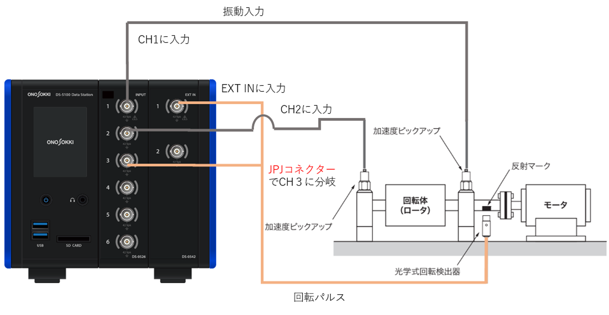
System configuration example for 2 surfaces and 2 conditions

  • System configuration example for 2 surfaces and 2 conditions

Case Studies

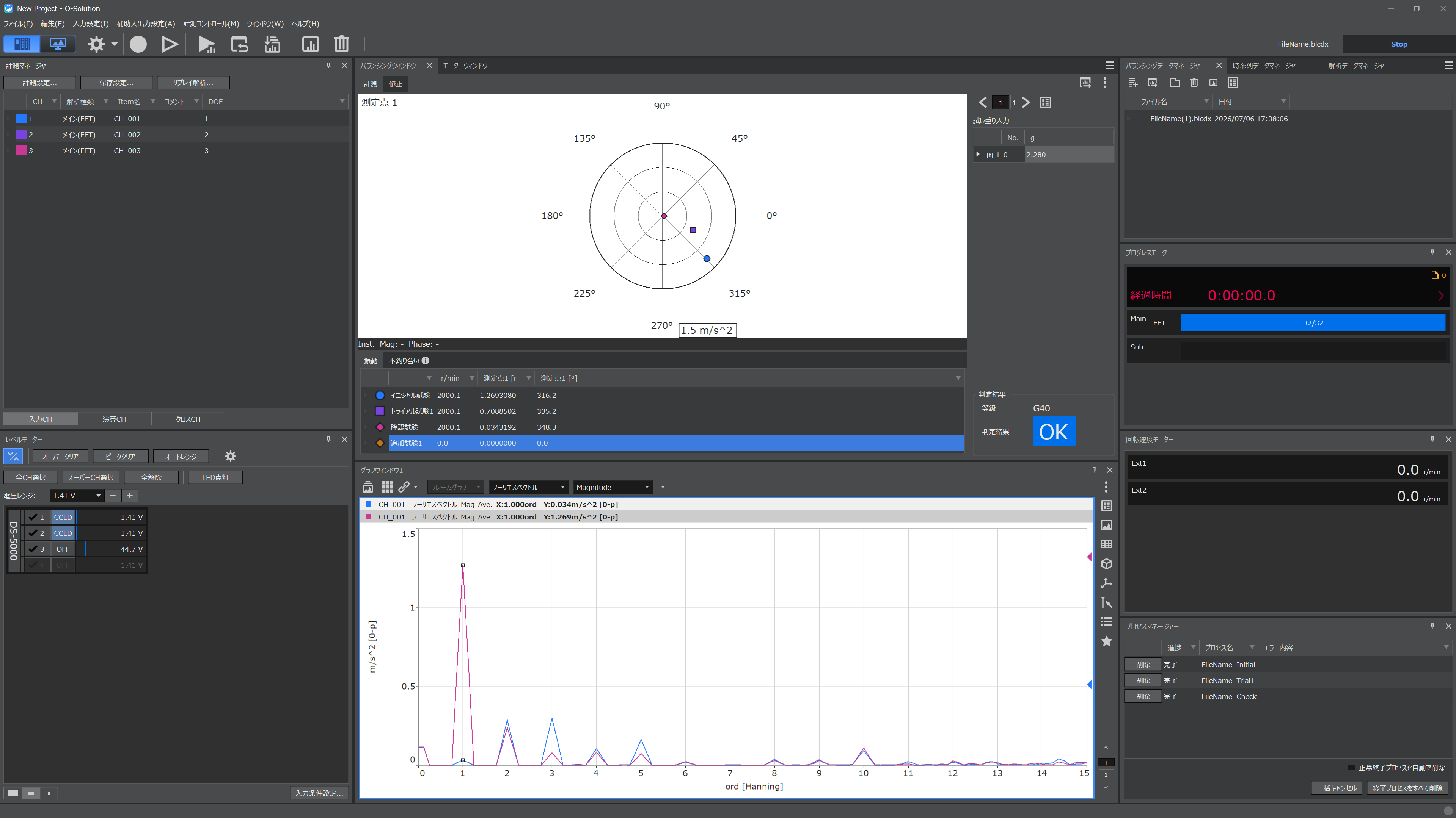
These are the measurement results of the rotor rotation imbalance correction performed using a brushless motor.

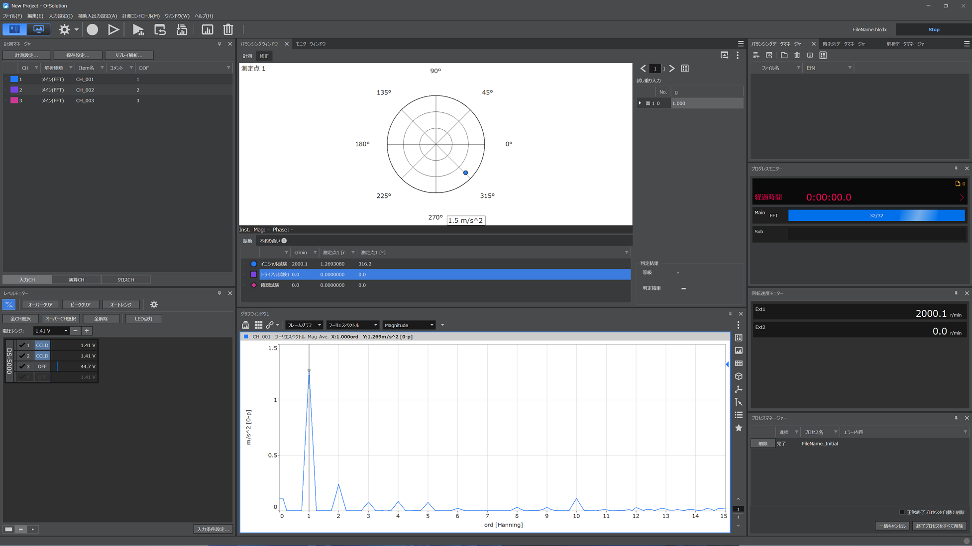
Initial test

Check the extent of the object's vibration.
Through Fourier order analysis, you can confirm whether it is a rotational first-order component caused by unbalance.

  • Initial test

Trial test

Attach the trial weight and rotate the object in the same manner as the initial test.
By entering the weight and position of the known trial weight and performing the measurement, the position of the correction weight is identified.

  • Trial test

Confirmation test

Attach the correction weight to the correction position and confirm whether the unbalance has been resolved.

  • Confirmation test

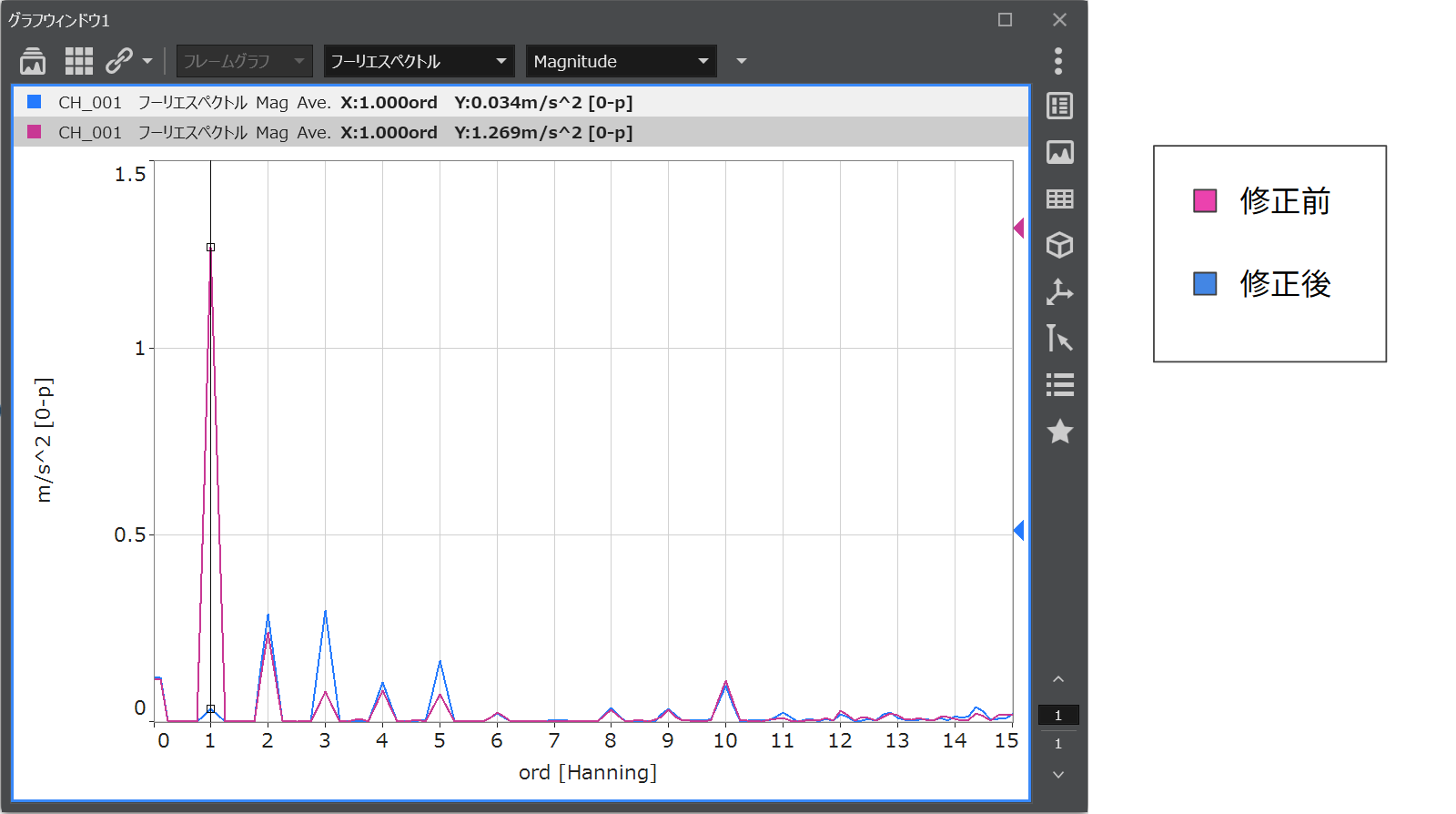
By overlaying the results of the initial test and the confirmation test, you can compare the differences before and after the balance correction.

  • Comparing the differences before and after balance adjustments

最終更新日:2026/08/10