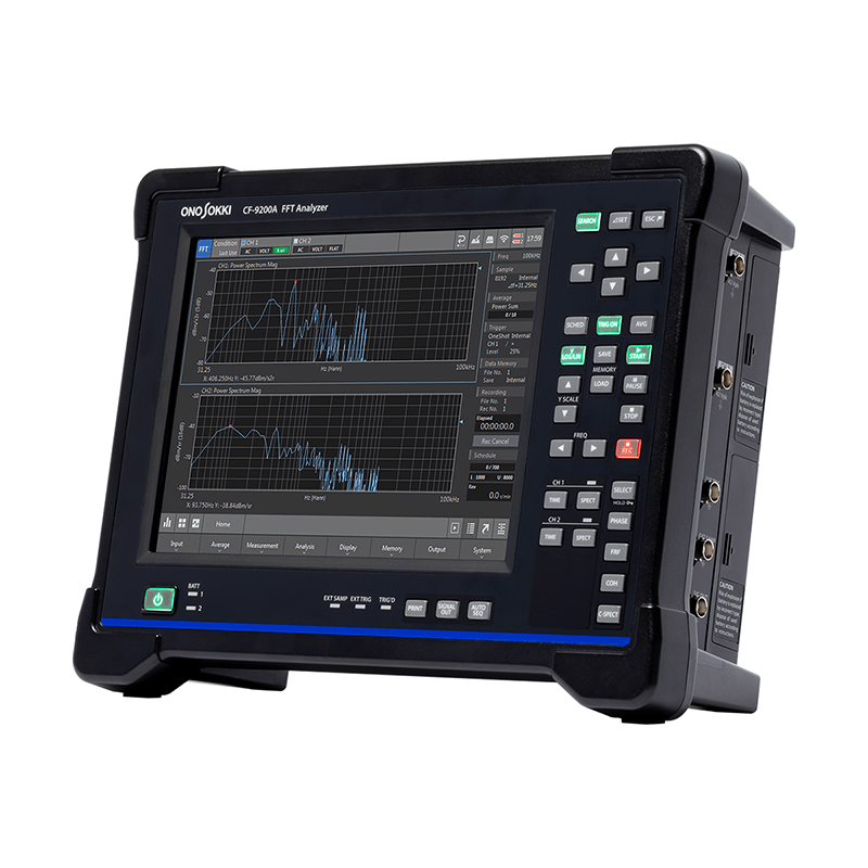
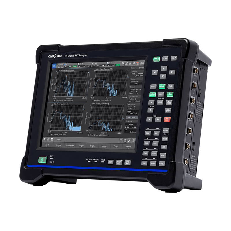
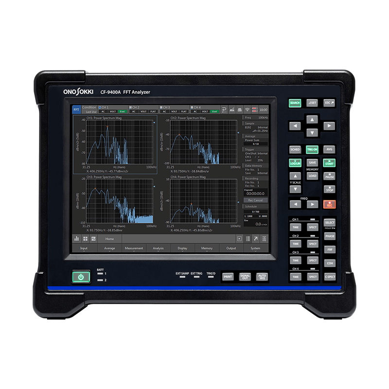
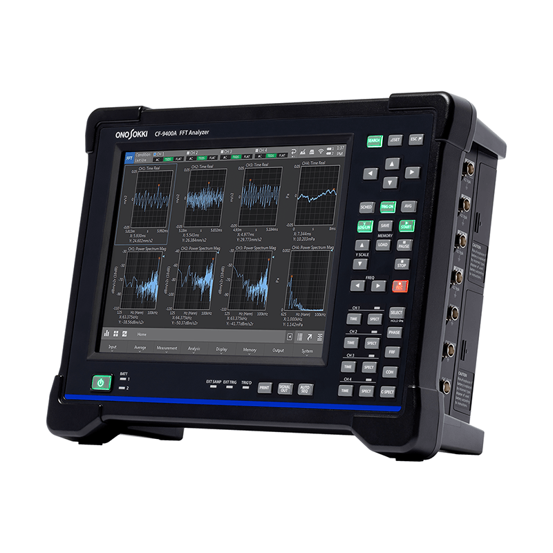
Portable 2-channel/4-channel FFT analyzer
CF-9200A/CF-9400A
Innovative features housed in a tough body.
The CF-9200A/CF-9400A (CF-9000A series) is an all-in-one, portable FFT analyzer. It does not require a separate analysis PC; all operations of the FFT analyzer can be performed using only the hard keys and capacitive touch panel on the unit itself.
A newly developed, specially designed 24-bit A/D converter and 100 kHz high-performance front-end enable easier and more reliable analysis of noise and vibration emitted from plant piping, pumps, motors, automobiles, railways, home appliances, and other mechanical and electrical/electronic components. It also meets the needs of on-site solutions requiring FFT analysis, such as resonance and frequency characteristic analysis of mechanical structures using electromagnetic vibration exciters and impulse hammers.

The CF-9200A/CF-9400A allows you to perform basic FFT analyzer operations such as display, measurement, stop, recording, and readout using large hard keys. This ensures reliable and speedy operation.
Setting the number of waveforms displayed and zooming in and out of the X and Y axes can be done intuitively using swipes and pinches on the touch panel. You can easily change to your desired scale.

The CF-9200A/CF-9400A features two high-capacity lithium-ion rechargeable batteries, enabling up to 8 hours of continuous cordless operation.
Furthermore, the hot-swap mechanism allows for battery replacement while the power is on, enabling measurement work to continue without interrupting analysis or recording tasks or requiring reconfiguration. The built-in battery can also be charged while in operation *.
* It takes approximately 7-8 hours to fully charge with the power on.
With the power off, it lasts approximately 7-8 hours (at an operating environment of 20°C).

This portable device condenses not only FFT analysis, real-time octave analysis (RTA) *1, and rotational tracking analysis *2, but also linear/log sweep analysis using signal output, and amplitude excitation control of electromagnetic exciters *3.
Simultaneous recording during analysis is possible, and offline analysis can be performed using the CF-9200A/CF-9400A unit or its peripheral software.
*1 Octave analysis function (CF-0923) is required.
*2 Tracking analysis function (CF-0922) is required.
*3 Log sweep/vibration control function (CF-0942) is required.

The CF-9200A/CF-9400A achieves high performance without a fan or spindle. It emits no mechanical noise or vibration. In acoustic and vibration measurement and recording environments, the CF-9200A/CF-9400A unit itself will not be a source of noise or vibration.
By installing a wireless LAN adapter, you can operate the CF-9200A/CF-9400A unit using a tablet or other device without touching the unit itself *.

The CF-9200A/CF-9400A allows for real-time simultaneous reading of frequency (Hz) and three amplitude values (acceleration (m/ s²), velocity (m/s), and displacement (m)) using a tripartite graph * 1.
Furthermore, by performing a 1/3 octave adjustment and displaying the VC curve *2 (Vibration Criterion Curves), it is possible to quickly determine the permissible vibration standards and installation environment evaluation for vibration-sensitive precision equipment such as AFMs, electron microscopes, and laser interferometers.
Unlike conventional methods that required individual differentiation and integration processing using frequency analysis functions to convert amplitude values, this new feature enables speedy reading of each amplitude value.
*1 The tripartite graph (Figure) allows for amplitude readings of acceleration (m/ s²) and displacement (m), based on velocity (m/s) on the frequency (Hz) axis.
*2 The VC curve is proposed as a standard for the acceptable level of micro-vibration when installing precision machinery. When using the VC curve, evaluation is performed at a 1/3 octave bandwidth, and the standard is divided into five stages (VC-A, VC-B, VC-C, VC-D, VC-E) in 6 dB increments, serving as a guideline for various applications, from optical microscopes to laser devices with long optical path lengths.
Generic Vibration Criteria for Vibration-Sensitive Equipment, Colin G.Gordon, SPIE99Evolving criteria for research facilities: I-Vibration

The CF-9200A/CF-9400A features a newly developed front-end with a 24-bit A/D converter, achieving a wide dynamic range of over 120 dB. This eliminates the need to frequently change the voltage range due to A/D overshoot, which was common in typical acoustic and vibration measurements.
The elimination of the need to redo measurements and data recordings has significantly accelerated measurement and analysis work, and it has also made it possible for novice users unfamiliar with FFT analyzers to use it with confidence.

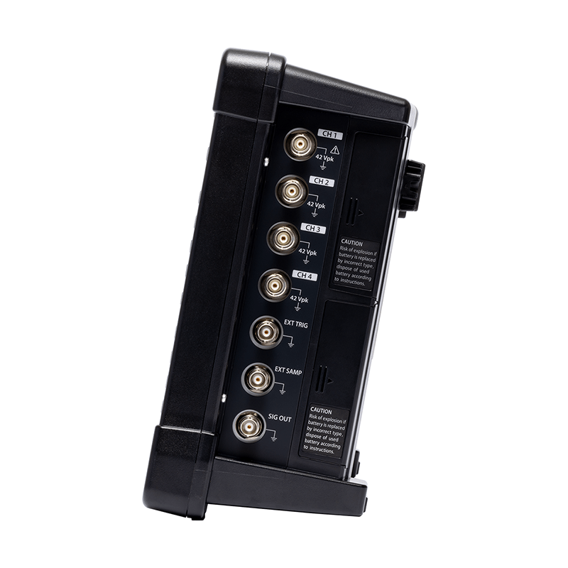
The CF-9200A/CF-9400A features complete isolation (isolation) of all signal input channels.
It offers high immunity to ground loops and noise superposition, enabling reliable measurements in measurement environments and targeting situations where potential differences are likely to occur.
Furthermore, it protects critical FFT systems from sensors and signals that may be exposed to dangerous transient voltages.

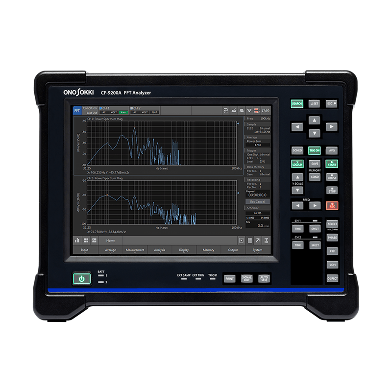
The CF-9200A/CF-9400A features a 10.4-inch LCD with a capacitive touch panel.
The FFT graph manipulation now utilizes gesture controls such as tapping and swiping. This allows for easy and intuitive scaling of the measurement bandwidth and gain.
Waveform amplitude graph scale fitting, waveform swapping, time and frequency axis scaling, waveform offset, and span adjustment can all be done with simple gesture controls.

The CF-9200A/CF-9400A uses newly developed large hard keys for power on/off, major operations, switching display data types, and saving data.
It provides quick and reliable operation even in unstable and confined spaces, preventing data loss and malfunctions.
It also features a lock function (HOLD) for the hard keys and touch panel to prevent accidental operation or setting changes due to unintended contact.

The CF-9200A/CF-9400A displays the main operating status of the FFT by illuminating LEDs.
LEDs are built into the main hardware keys, as well as the startup process, the charge status of the built-in rechargeable battery, and the A/D converter's Over status, allowing the operator to monitor the FFT's operation status even from a distance.

Automatically detects cable breaks or connector failures in Accelerometer and microphones *.
This prevents problems before the actual measurement takes place.
The CF-9200A/CF-9400A also allows you to disable the wire break detection function.
* Built-in constant current drive (CCLD) type preamplifier

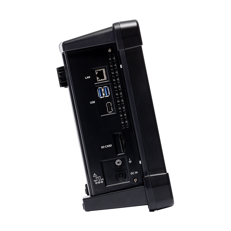
By connecting the CF-9200A/CF-9400A to a Windows® PC using a LAN cable, you can copy and write various measurement data, operate the PC using the remote desktop function *1, and project the CF-9200A/CF-9400A screen using a projector.
Furthermore, by using the optional LAN external control function (CF-0947), the CF-9200A/CF-9400A can be controlled programmatically.
PC requirements: Windows® 10 (32-bit and 64-bit versions)

By attaching a wireless LAN adapter *2 to the CF-9200A/CF-9400A unit, you can wirelessly transfer FFT data and record data stored on the CF unit to a Windows® PC.
Furthermore, by using the remote desktop function *1, you can view the screen and remotely control the CF-9200A/CF-9400A series from a Windows® PC or various portable information terminals.

By attaching a short-range wireless communication adapter *2 to the CF-9200A/CF-9400A unit, you can wirelessly print graphs from the display screen to a mobile printer *3 simply by pressing the "PRINT" button on the unit. You can also connect keyboards and other devices wirelessly.

It performs A/D conversion on voltage signals from sensors such as vibration, noise, strain, and current probes, and displays them as time-domain data.
You can directly read the X and Y axis values of any point using the search cursor, and easily read time differences and level differences using the delta cursor function.
The time-axis statistical analysis function allows for quantitative analysis of time-based waveforms such as the mean (MEAN), effective value (RMS), and crest factor, as well as anomaly diagnosis.

The power spectrum is calculated by performing FFT analysis to determine the intensity of each frequency component contained within the captured time-domain waveform, calculating the power for each frequency bandwidth (frequency resolution Δf), and then graphing it with frequency on the horizontal axis.
Power spectrum analysis allows for the measurement of vibration and noise levels, equipment anomalies that are difficult to estimate from time waveforms alone, and the natural frequencies of structures.

The frequency response function (FRF) in mechanical or electrical circuits represents the ratio of input to output on the frequency axis using gain and phase characteristics.
The gain characteristic represents how the amplitude changes as the input signal passes through the transfer system being evaluated, with the Y-axis representing the ratio of the output amplitude to the input amplitude.
The phase characteristic indicates the phase lead or lag between the input and output signals, and the Y-axis is displayed in degrees or radians.

The tracking analysis function (CF-0922) automatically saves vibrations, noises, and other phenomena generated when various rotating machines rotate in the low to high speed range while performing FFT analysis, and allows for the analysis of physical phenomena such as vibrations and noises that change with speed, based on the rotational speed.
Rotating machinery, such as engines, gearboxes, turbines, and electric motors, operates across a wide range of speeds, from low to high RPMs. At certain rotational speeds, the components can resonate, generating significant vibrations and noise. To reduce the risk of damage and improve the quietness of the equipment, it becomes necessary to evaluate the relationship between rotational speed and the natural frequencies of the components.
The tracking analysis function (CF-0922) allows you to visualize and analyze the relationship between rotational speed and the resulting physical phenomena from various perspectives, such as color maps, three-dimensional graphs, and order components based on one rotation, for a specified range of rotational speeds.

An octave refers to twice the frequency, and because the frequency response perceived by the ear is geometrically uniform, octave analysis (CF-0923) is effective for noise analysis.
Within the frequency range of the noise being measured, the sound pressure level for each band can be determined by passing it through a bandpass filter specified to a 1/1 octave or 1/3 octave standard.

The Log Sweep function allows you to continuously change the frequency of the driving sine wave from the 1-channel signal output module (CF-0971) and evaluate the resonance point of the target transmission system.
By performing a sine sweep on the frequency axis using a logarithmic scale, the gain and phase can be determined for each frequency, allowing for the acquisition of an accurate response function with a high signal-to-noise ratio.
Furthermore, the excitation control allows the amplitude of the exciter to be controlled within an arbitrary range during excitation and sweeping, enabling excitation tests to be conducted without considering the frequency characteristics of the electromagnetic exciter.

* The Log Sweep/Excitation Control function (CF-0942) requires a 1-channel signal output module (CF-0971).


-
* Note: If you are using a TEDS-compatible sensor from another manufacturer: Depending on the type of TEDS-specific chip inside the sensor, it may not be possible to read TEDS information.
1. If you are considering purchasing sensors from other manufacturers, please contact the respective TEDS-compatible sensor manufacturer or retailer to confirm their operation.
2. If you wish to use your existing TEDS-compatible sensor with our TEDS-compatible measuring instrument, please have it tested using our demo unit. (Please contact your nearest sales office.) -
size 10.4-inch Resolution 800 x 600 pixels method TFT color LCD capacitive touch panel Brightness adjustment Bright/Dark (2 levels) Lighting (backlight) LED * While TFT color LCD displays are manufactured using highly advanced technology, some pixels (dots) may be non-illuminated or constantly illuminated. The effective dot ratio is 99.999% or higher for an 800x600 dot display. Color unevenness and brightness unevenness may be visible depending on the viewing angle and temperature changes, but these are not defects, and therefore we cannot accept exchanges or returns. Please understand this in advance.
-
Power switch Press and hold for about 1 second to turn the device on or off. If you continue to press and hold while the device is on, it will force a power off. Soft keys Detailed settings for each function can be configured using the soft keys below the LCD screen. Direct Key Cursor & Selector Keys Up/down/left/right, SEARCH, ⊿SET, ESC Measurement unit switch SCHED, TRIG ON, AVG, START, STOP, etc. Waveform selection section TIME, SPECT, PHASE, FRF, COH, C-SPECT, SELECT Erroneous operation prevention function Press and hold SELECT to lock and unlock soft keys and direct keys (excluding the power switch). Print key PRINT: Direct printing of screen display when connecting a recommended printer. Auto Sequence Playback Key AUTO SEQ plays back registered sequence of operations. Frequency range switching key FREQ left and right Y-axis scale toggle key Y SCALE Top and Bottom Signal output ON/OFF SIGNAL OUT (Effective when CF-0971 option is installed) -
frequency range 100 mHz to 100 kHz Frequency accuracy ±0.005% (±50 ppm) of the reading Sampling Frequency Frequency 2.56 times the analysis range (during internal sampling) Sampling points / Analysis points Sampling points Analysis points 256 100 512 200 1024 400 2048 800 4096 1600 8192 3200 16384 6400 Overlap processing MAX/66.7%/50%/0%/Optional window function Rectangular / Hanning / Flat Top / Force / Exponential / User Defined Delay function It is possible to delay the time frames of other channels by 0 to 8191 points relative to CH1. Time waveform processing function First and second derivatives / single and double integrals
Absolute value conversion / DC cancellation / Trend removal / SmoothingFFT Real-time Rate 100 kHz/4CH (FFT frame length 2048 points or less, internal sampling) Averaging function Number of times averaging is set 1 to 65535 times Averaging setting time 0.1 to 999 seconds, in 0.1-second increments. It is possible to stop the average at either the number of trials or the time interval. time domain Averaged average / Exponential average frequency domain Additive average / Exponential average / Peak hold / Subtractive average / Sweep average / Fourier average / Max overall amplitude area Average A/D over-cancellation / double hammer cancellation function / averaging allow selection function (ADD+1) / averaging undo function Trigger function When triggered, the LED (TRIG'D) blinks green. Trigger level -99 to 99 (Unit: %) Default = 25%
Thresholds can be set using amplitude units (including user-calibration values).Hysteresis Level 0-99 (Unit: %) Default = 2% position ±16383 mode Free / Repeat / Single / One Shot sauce CH1/CH2 (CF-9200A) to CH3/CH4 (CF-9400A) / External trigger input slope +/-/± (Internal trigger) +/- (External trigger) FFT operation 32-bit floating-point (IEEE single-precision format) -
time domain Time-domain waveform / Autocorrelation function / Cross-correlation function / Impulse response / Cepstrum amplitude area Amplitude probability density function / Amplitude probability distribution function frequency domain Power spectrum / Fourier spectrum / Lifted spectrum / Cross spectrum Calculation function (time-axis statistical processing) Mean value / Absolute value / Mean value / RMS value / Standard deviation / Maximum value / Minimum value
Crest factor / Skewness / Kurtosis -
Recording device You can choose between internal storage or an SD/SDHC memory card. Record function frequency range 100 kHz (max) Recording Channels CH1/CH2 (CF-9200A) CH1~CH4 (CF-9400A),
Rotation information can also be recorded.Recording time 4 GB: Approximately 32 minutes, 50 kHz range, 4-channel recording, rotation information OFF, 2048 sample points. Recording format ORF Maximum recording capacity SD/SDHC/SDXC (up to SDXC 128 GB) data file 9990 (999 data x 10 blocks) data
DAT/TXT/BMP (Analysis data can be recorded simultaneously in three different formats (TXT and BMP are selectable))File formats Analysis data can be recorded simultaneously in three different formats (TXT and BMP are selectable).
DAT/TXT/BMP (List data can also be saved when saving as TXT)Panel Condition Memory Store and recall measurement conditions (up to 50 types) Handwritten notes It remembers handwritten notes written on the touch panel. -
USB Number of ports 3 (USB3.0 x 2, USB2.0 x 1) USB (Type A) For USB flash drives (USB 3.0 and USB 2.0), wireless LAN modules, and Bluetooth® adapters. Wireless connection Wireless LAN module Recommended products from TP-Link Bluetooth® adapter Recommended products from TP-Link SD card slot Number of slots 1 Supports SD / SDHC / SDXC cards. Capacity: up to SDXC 128 GB
(We do not guarantee the operation of all SD/SDHC/SDXC cards.)LAN Number of ports 1 10BASE/100BASE-TX/1000BASE-T Remote desktop, external control Printer output Print using the PRINT key on the device. Interface USB or Bluetooth® (when using a TP-Link Bluetooth® adapter) Compatible printers MW-270, manufactured by Brother Industries, Ltd. Output data Screen copy / List view copy -
Condition View Display the list of settings conditions clock Display year, month, and day, hour, minute, and second. Operation confirmation sound / warning sound Can be turned on/off arbitrarily -
Power supply Included AC adapter or included battery Power consumption CF-9400A
(When the CF-0971 signal power option is installed)87 VA or less (when using AC adapter, battery not charged) 150 VA or less (when using an AC adapter and charging the battery) CF-9200A
(When the CF-0971 signal output option is installed)73 VA or less (when using AC adapter, battery not charging) 150 VA or less (when using an AC adapter and charging the battery) Operating temperature range 0 to +40°C (humidity 20 to 80% RH, non-condensing) Storage temperature range -10 to +50 °C (including lithium-ion rechargeable batteries) (humidity 20 to 80 %RH, non-condensing) Functional ground terminal Noise reduction grounding terminal Outline drawings Less than 333 (W) x 248 (H) x 112 (D) mm *Excluding handlebars, stand, and protrusions 
Main unit cooling Natural air cooling (fanless) Weight Approximately 3.8 kg without battery Approximately 4.8 kg with two batteries installed. CE marking Low Voltage (LVD) Directive 2014/35/EU Standard EN61010-1
EMC Directive 2014 / 30 / EU Standard EN61326-1
RoHS Directive 2011 / 65 / EU Standard EN IEC 63000Accessories AC adapter (AC adapter power cable (2 m)) Quantity 1 Battery (RRC2020 (100496-15) Lithium-ion secondary battery) quantity 2 Instruction Manual (CF-9200A/CF-9400A User's Guide Booklet) Quantity 1 CD-ROM (Reference guide, utilities, DLLs for external controls, etc.) Quantity 1 SD card (4 GB) Quantity 1 -
Input voltage AC 100-240V Input Frequency 50/60 Hz Output voltage Rated 16V Output current Rated 4A safety standards PSE/CE/UL/GS -
battery Lithium-ion rechargeable battery Built into the main unit (hot-swappable) quantity 2 pieces can be installed Operating time 8 hours of continuous operation (with 2 new batteries installed)
4-channel 100 kHz analysis / Signal output OFF / LCD backlight (bright) /
USB port not usedBattery status display Main screen When a rechargeable battery is installed, the remaining capacity is displayed on the device screen. Battery LEDs (BATT1, BATT2) Orange light when charging, green light when fully charged.
(When AC adapter is connected)When the battery is low, the indicator lights up red (it lights up when the battery level is below 5%).
(When running on battery power without AC adapter)A low battery warning message is displayed when the battery level is below 15%. Processing when remaining battery level is at its lowest When the battery level drops below 3%, a low battery warning message is displayed and the device automatically shuts down. Remembers the previous panel condition. Charging time When the main unit is in operation Approximately 7 to 8 hours (depending on usage) When power is OFF Approximately 7-8 hours External charger (recommended) Approximately 4.5 to 5 hours -
Number of Channels 1 Output terminal shape BNC (C02 type) Isolation Non-insulated Output Voltage Swing ±1 mV to ±10 V (amplitude + DC offset) Output format unbalanced output Output coupling DC protection circuit Short-circuit protection Output Independence 0 Ω or 50 Ω ± 10% Maximum Output Current 10 mA Offset Voltage ±10 V D/A converter 16-bit Conversion rate up to 512 kHz D/A converter 16-bit Output waveform Sine wave / Swept sine wave / Pseudo-random / Random / Impulse THD and spurious -75 dB or less (sine wave 1 kHz, amplitude ±1 V output) Adaptive FFT analysis length 256~16384 Zoom Analysis Support (linked to zoom analysis range) Voltage amplitude accuracy Within ±0.5 dB (at 1 kHz, 1 V0-p, 1 MΩ load) Frequency accuracy ±50 ppm Digital Filter Smoothing filter When a rechargeable battery is installed, the remaining capacity is displayed on the device screen. When zoomed in: 6th degree ellipse Octave band filter 1/1 or 1/3 octave 6th Butterworth Pink filter Analog system: -3 dB/oct ±1.0 dB (specified for 20 Hz to 20 kHz) Burst function Single burst, continuous burst Burst cycle sine wave Cycles 1-32767 Swept sign / pseudo-random / impulse 1-32767 FFT frames random 1 ms to 32 s Cycle setting unit
and burst intervalsine wave One cycle of a sine wave Swept sign / pseudo-random / impulse 1FFT frame random 1 ms Taper Function The output can be gradually increased or decreased when the signal is turned ON/OFF. 1 ms to 32 s (in 1 ms increments) However, this function is disabled when the burst function is ON. Spectral flatness 20 kHz to 100 kHz: within ±1.0 dB 0–20 kHz: Within ±0.2 dB Crest Factor sine wave Approximately 1.41 Swept sign Approximately 1.4 to 1.6 Pseudo-random 3.3 or less random 3.3 or less Impulse 32.0 or less