本文にスキップする

Select your region & language

Global

Region

Technical Report: Coefficient Representing Damping Characteristics 3

4. Summary of Relationships

The interrelationships of the coefficients representing attenuation are summarized below.

5. Conclusion

Since vibrations are an unavoidable phenomenon when machines operate, it is crucial in machine design to keep vibrations below acceptable levels. In particular, the phenomenon of resonance can cause large vibrations even from small external forces, requiring significant caution. Ideally, one would want to separate the resonance frequency (natural frequency) from the frequency of forced vibrations, but in reality, the natural frequency often falls within the operational range, which is a headache for designers.

As explained in this paper, the behavior of resonance is significantly affected by damping. Therefore, it is possible to design systems that incorporate appropriate damping in advance to keep vibrations below acceptable levels. Additionally, when reducing vibrations in problematic machinery or structures, it is common to add damping elements such as dampers. In such cases, the knowledge about damping discussed in this paper serves as a foundation. The vibration model addressed here is a one-degree-of-freedom system, and the applied external force is a simple sinusoidal model; however, actual machinery and structures are more complex systems, and the external forces are irregular waveforms. Moreover, the value of the damping ratio can change depending on the amplitude and conditions, making actual vibration analysis not straightforward. Nevertheless, the basics of mechanical vibration are represented by the one-degree-of-freedom model explained here, and the general behavior of vibrations can often be described using the knowledge presented in this paper, which should provide a starting point for analysis and countermeasures.

In summary, I have briefly explained the meaning of the coefficient representing damping, centered around the damping ratio, and how to calculate it. The content of this article is common knowledge for designers of machines and structures, but I hope it serves as a useful reference for those who are not specialists in vibrations when considering vibration control.

[Supplement] Derivation of the formula for the half-width method.

The formula for maximum amplitude (22) can be obtained by substituting the formula for resonance frequency into the formula for amplitude ratio (21).
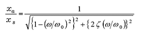
 img-dampingfactor3-02 (21) 


the formula for the resonant frequencyimg-dampingfactor3-12From this, in equation (21)img-dampingfactor3-13if substituted;

 ["img-dampingfactor3-03"] (22)


From equations (21) and (22), the amplitude is the maximum amplitude ofimg-dampingfactor3-14to find the frequency that becomes;

 img-dampingfactor3-04 (28) 


When organized;

 img-dampingfactor3-05 (29)


When you solve this;

 img-dampingfactor3-06 (30)

 img-dampingfactor3-07 (31)


If ζ ≪ 1, then ζ² ≒ 0.

 ["img-dampingfactor3-08"] (32)

 img-dampingfactor3-09 (33)


img-dampingfactor3-15If we assume;

 img-dampingfactor3-10 (34)

 img-dampingfactor3-11 (35)


As shown above, the formula for calculating the damping ratio ζ from the half-width is an approximation valid for ζ ≪ 1, so accurate calculations can be made when ζ is 0.05 or lower, and tolerating some error, it can be up to 0.1.

[Reference] Damping ratio of structures and machines

The damping ratios of actual structures and machines are generally as follows.

steel frame building 0.003 〜 0.04
mid-rise buildings (10 stories or less) 0.005 〜 0.12
high-rise building 0.02 〜 0.1
steel tower 0.002 〜 0.03
concrete tower 0.01 〜 0.02
road bridge 0.02 〜 0.05
suspension bridge 0.002 〜 0.08
suspension of a large passenger vehicle 0.1 〜 0.3
suspension of a small passenger car 0.2 〜 0.5
motorcycle suspension 0.35 〜 0.45


Reference Material

1. 'Controlling Vibrations' Kohei Suzuki (Ohmsha)

2. 'Encyclopedia of Automotive Engineering Volume 11' (Sankai-do)
